What's new
Pinball info

Register a free account today to become a member! Once signed in, you'll be able to participate on this site by adding your own topics and posts, as well as connect with other members through your own private inbox!

2 niggles with the Flintstones

unity_neil

Registered
10 Years
Joined
Oct 14, 2012
Messages
301
Location
Nuneaton
Hi there, I have a couple of little issues and wonder if someone might help a newbie out.

When shotting a ball softly around the left lane to the bronto crane (see point 2) sometimes the ball activates the crane, but gets stuck, normally its fine. Lifting the playfield vertically frees the offender, but obviously stops your game.
I've tried leaning over with the glass out and mirrors but cant see the issue and it underneath the "machine" which I dont feel comfortable taking apart yet.

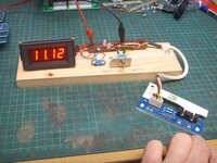
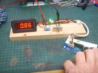
Secondly, the right flipper (lower) goes weak when the machine has been on for a while, but then can suddenly get a boost of strength, before wekening up again. upper and left flippers are fine. the coil does get slightly warmer than the left, although not "Hot". I have no idea what an opto looks like (ref another thread on here) but do have a mutimeter and soldering iron. does anyone have any pictures?

Many thanks in advance.

Neil
 
The opto is on the small board right near the flipper buttons. Pressing the flipper button bends a metal strip "out of the way" of the opto. The opto is a U shaped bit of plastic. When the fault occurs next go into test mode and see if the flipper concerned works in high-power mode or (as it would seem) just low-power "hold" mode. If it's intermittant then it could be anything to do with the flipper - the coil, the diode, the driving transistors or a wiring fault. Check the diode (or even replace them at a huge cost of 4p each and in doing so you'll also resolder the coil / lug windings) as a first step.
 
hmm so here is a pic of the underside of my PF near the right flipper coil. The contacts you can see are made when the flipper is in the up position, does this replace the optos you were referring to?

i397.photobucket.com_albums_pp51_unity_n_93df0b94_4fa0_4e13_9c7b_4420e7c1625c_zpsdf4cb425.jpg
 
Doh! reread the post and xenon did say flipper button, brain stopped after seeing flipper o_O

sooooo. heres the board:

i397.photobucket.com_albums_pp51_unity_n_temporary_zpscbf2f0e1.jpg

no sign of a diode....?
 
Broto crane issue. I suspect this might the same issue as I had. The ball goes as far as the one way gate and then doesn't fall back into the VUK hole and instead sits there. There's a wire ball guide inside this that needs to be bent slightly backwards to ensure the ball rolls backwards rather than sitting to the left of the gate. If you take the broto plastic off you should be able to see it.
 
In your picture you can clearly see the two optos with the plastic "beam breaker" that moves with the flipper button. I won't be this though because your flipper is flipping - just not at the required power.

As Calimori said, the diodes are on the flipper coils themselves. Again, not likely to be the problem but they can break down when they get hot. Changing them will also reflow the coil lugs because they're soldered to the same thing.

I suspect it's the coil itself.
 
Flipper going weak could be due to the flipper opto board not working correctly and the flipper is overheating.

See the the following thread :-

http://www.pinballinfo.com/community/threads/overheating-flipper-coil.2962/

Andy from Pinball Mania recommends checking the voltage on SW1 and SW2 when the optos are open. (Flipper button pressed).

Do you have a multimeter?

As detailed in the other thread the voltage on SW1 and SW2 should ideally read under 1 volt when open. Under 2.5 volts is ok but anything over can cause issues.

Personally I still haven't resolved my issue, I replaced the opto switches on the board but it still didn't work. I even bought a replacement flipper opto boards from www.pinballcenter.eu and they were useless.

Wizcat from this forum tested one of his boards and it read over 1 volt when open. He gave it a clean with a toothbrush and it brought down the voltage reading!! I'm pretty sure the toothbrush wasn't loaded with Colgate but you never know? ;)

I'm waiting on a reply from www.homepin.com regarding a replacement board on their site. His board has extra components on it to hopefully sort out voltage issues. I've just contacted him to see whether it will sort me out. I will keep the forum informed.

Too much info..?
 
well a wipe over of the opto seems to have rejuvenated the flipper! I'll keep playing and update....
 
Only just seen this thread. Yeah, cleaning the opto may help because the opto receiver is basically a transistor that should sink the current when it is open. If it isn't receiving enough light, then the current doesn't drop low enough for the LM339 comparitor to work correctly.

The LM339 is basically looking for the 12v to drop well below 5v. If it only gets close to that then the logic boards aren't sure if the flipper is pressed or not, so it ends up toggling the flipper high power on and off rapidly, causing overheat and eventually fatigue.

If the issue is on the opto board (as described above) then cleaning may help, reflowing solder joints could be worth a try. Onze has really been through all these issues and more, but I expect he'll be doing another update very soon :)
 
The optos used in the original boards were a special type that switched down hard. Common replacements available from most electronic sources simply don't.

I had to throw out 200 boards when I found the original optos were no longer available in the quantities I needed for production and the ones I did find were stupidly priced.

I re-designed the circuit (as simple as it is) and added a transistor that pulls the output line below 1V. I then did this with both types of flipper board - Type1 & Type2 and have had excellent results and reports from all buyers since doing this.

You can see the extra parts used in the pictures with the links below - I had no option but to go SMD on the Type2 boards as there isn't enough "real estate" to use through hole parts:

http://www.homepin.com/fo.html
http://www.homepin.com/fo2.html
I've just installed the Type1 boards in my BSD and they're working great.

Buy with confidence from HomePin his products and customer service are second to none.
 
I don't think many people are aware of the issues with 'new' optos, so worth repeating...

Williams went out of their way to design and manufacture a unique opto receiver that could sink the 12ma or so of current. When they went bust (and the original opto no longer available) some manufacturers are using (or recommending as replacement) qve11233 or opb824 optos. Neither of those can sink the current sufficiently. They either don't work at all, or produce the same behaviour (flipper coil overheating)

Onze went through a few different suppliers before finding Homepin. They seemed to be the first to understand the issues and have developed a solution where the optos is used as a predriver for a transistor that CAN sink the current correctly.

Incidentally, I noticed the other day that Fairchild Semi have ceased production of the qve11233 optos as of a week or two ago.
 
I made up a simple little test jig so that every board we build can be fully checked before packing. The pics show the voltage on the output (switch) line of the board in both open and closed positions.

opto_closed.jpg
[/IMG]
 

Attachments

  • opto_closed.jpg
    opto_closed.jpg
    31.1 KB · Views: 8
  • opto_open.jpg
    opto_open.jpg
    28.5 KB · Views: 8
Back
Top Bottom