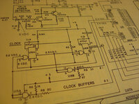
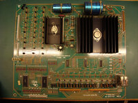
oh yeah,can't resist
Pinball info
You are using an out of date browser. It may not display this or other websites correctly.
You should upgrade or use an alternative browser.
You should upgrade or use an alternative browser.
In Progress 1983 Bally GOLD BALL - Further Adventures in Budget Restoration
- Thread starter Nedreud
- Start date
cpc give free delivery - i only ordered £9 odd the other day(14th),wasn't charged extra and got free 3=5 day delivery it arrived today
Free delivery on web orders over £5
I keep forgetting about CPC. Thanks for the tip @TYHO. It's all swings and roundabouts. I can never seem to get everything from one place in one order without getting stung on something. I ordered a hundred 2Nxxx transistors from eBay yesterday because it was the cheapest of anywhere and free postage. But I couldn't find a deal on some other 2N trannies for anything less than about 15p each. Way too much!
And I was going to order some stuff from Pinball Centre: a gold ball, a 5101 SRAM chip and a gold-coloured plastic backglass lift channel. Even though that's all well under 1kg it was going to cost €20 because the lift channel is a large item so has to come in a bigger parcel size! Well nuts to that!
And I was going to order some stuff from Pinball Centre: a gold ball, a 5101 SRAM chip and a gold-coloured plastic backglass lift channel. Even though that's all well under 1kg it was going to cost €20 because the lift channel is a large item so has to come in a bigger parcel size! Well nuts to that!
Time for another progress update on the MPU repairs. Last time I'd got it unlocked and fully booting passing all 6 tests running the original PARAGON ROMS with factory jumper settings. I then said my next step would to remove the factory jumpers and fit 0.1" header pins on all the "E" sockets so I could re-jumper this board in a matter of seconds for any combination of original masked ROMS or EPROMS.
Well... that was my plan! Powered the board up one last time to check it was still working. Oh dear, only 2 flashes. No third flash means something is wrong with the 5101 SRAM at U8. Put the 5101 back in the PARAGON MPU and checks out fine, so the chip is good. Drat!
Right. Time to stop dilly-dallying and get rid of the crap DIL socket at U8. Hacked the black plastic frame to bits with snips, unsoldered the pins and then cleaned up the tracks and pads with flux cleaner and fibreglass pencil. Oh dear... can you spot the problem?
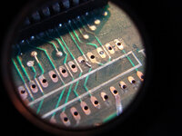
The topside track that passes between pins 15 and 16 is cracked and has started to lift! Time for some repairs! Cut off the lifted part, scrape off the green mask, clean and tin the freshly exposed tracks:
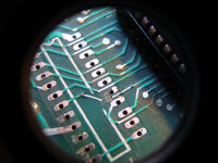
Then cut a piece of fine wire to length, strip and tin the ends, and solder it in place on top of the tracks:
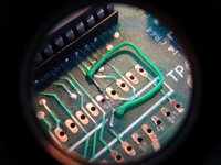
(In case you're wondering why the photos are round I took them through my 3.5x jewellers eyepiece for extra macro close-ups!)
Next, solder in place some quality gold turned-pin SIL socket strips ensuring the solder flows all around the pins and pads on both sides of the board:
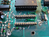
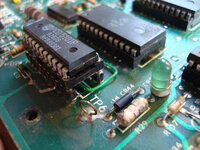
And here's the 5101P SRAM re-fitted. I keep it in an extra turned-pin DIL socket as I only have the one so have to keep swapping it back and forth between GOLD BALL and PARAGON. Better to break a DIL socket than a rather expensive and obsolete memory chip:
After that little lot I ditched all the wire ROM jumpers and fitted the 0.1" header pins to all the "E" sockets that are used to configure different types of ROM/EPROM. I then used 10cm colour jumper wires commonly used for Arduino/RasperryPi prototyping to configure the board for having the PARAGON factory ROMS U1, U2 and U6, which are all type 9316 (http://techniek.flipperwinkel.nl/ballyss/rep/index3.htm#35roms):
1-4, 2-6, 7-8, 9-11, 12-36, 13-15, 16a-19, 31-32, 33-34
Woohoo! 6 flashes, we are back in business. It was then a simple matter of pulling the PARAGON ROMS, popping in the previously untested GOLD BALL EPROMS (there are only two EPROMS; U2 which is a type 2532 and U6 a type 2732) and re-jumpering the board for this combination (http://techniek.flipperwinkel.nl/ballyss/rep/index3.htm#35roms):
4-12, 7-8, 10-11, 13a-14, 16a-29, 31-32, 33-35
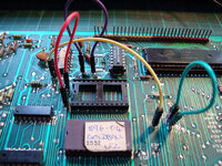
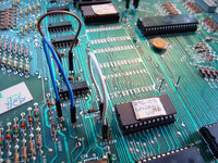
What do you know? The EPROMS are good! We have a working MPU for GOLD BALL! And with the jumper mod it's ready and able to test any other ROMS in the future just by moving a few wires around.
AWESOME! I love electronics!
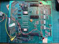
Here's the whole board powered up and running on the test bench (I use on old slimline ATX computer power supply - see my PARAGON shop log for the setup). There's not much to see but I assure you it's alive and kicking!
Well... that was my plan! Powered the board up one last time to check it was still working. Oh dear, only 2 flashes. No third flash means something is wrong with the 5101 SRAM at U8. Put the 5101 back in the PARAGON MPU and checks out fine, so the chip is good. Drat!
Right. Time to stop dilly-dallying and get rid of the crap DIL socket at U8. Hacked the black plastic frame to bits with snips, unsoldered the pins and then cleaned up the tracks and pads with flux cleaner and fibreglass pencil. Oh dear... can you spot the problem?

The topside track that passes between pins 15 and 16 is cracked and has started to lift! Time for some repairs! Cut off the lifted part, scrape off the green mask, clean and tin the freshly exposed tracks:

Then cut a piece of fine wire to length, strip and tin the ends, and solder it in place on top of the tracks:

(In case you're wondering why the photos are round I took them through my 3.5x jewellers eyepiece for extra macro close-ups!)
Next, solder in place some quality gold turned-pin SIL socket strips ensuring the solder flows all around the pins and pads on both sides of the board:

And here's the 5101P SRAM re-fitted. I keep it in an extra turned-pin DIL socket as I only have the one so have to keep swapping it back and forth between GOLD BALL and PARAGON. Better to break a DIL socket than a rather expensive and obsolete memory chip:

After that little lot I ditched all the wire ROM jumpers and fitted the 0.1" header pins to all the "E" sockets that are used to configure different types of ROM/EPROM. I then used 10cm colour jumper wires commonly used for Arduino/RasperryPi prototyping to configure the board for having the PARAGON factory ROMS U1, U2 and U6, which are all type 9316 (http://techniek.flipperwinkel.nl/ballyss/rep/index3.htm#35roms):
1-4, 2-6, 7-8, 9-11, 12-36, 13-15, 16a-19, 31-32, 33-34
Woohoo! 6 flashes, we are back in business. It was then a simple matter of pulling the PARAGON ROMS, popping in the previously untested GOLD BALL EPROMS (there are only two EPROMS; U2 which is a type 2532 and U6 a type 2732) and re-jumpering the board for this combination (http://techniek.flipperwinkel.nl/ballyss/rep/index3.htm#35roms):
4-12, 7-8, 10-11, 13a-14, 16a-29, 31-32, 33-35


What do you know? The EPROMS are good! We have a working MPU for GOLD BALL! And with the jumper mod it's ready and able to test any other ROMS in the future just by moving a few wires around.
AWESOME!
Here's the whole board powered up and running on the test bench (I use on old slimline ATX computer power supply - see my PARAGON shop log for the setup). There's not much to see but I assure you it's alive and kicking!

Last edited:
Cracking detective work there Gromitt 
That is awesome, do you have a really fine tip on your soldering iron to get in under the SIL socket strips?
to get in under the SIL socket strips
You dont - it's heated from the other side using the iron on the pads... the solder should work it's way through the hole under heat... as long as they are through-plated
That's the theory @Paul! In practice on these old and frankly cr@p quality PCB boards I did rework a few of the pins from the topside after I'd done the underside to make sure there was a solid electrical connection. After I pulled the original DIL socket most of the topside pads were still copper coloured as the solder had not flowed through fully from the back!
My soldering iron @Carl Spiby is an old Weller SI25D 25 Watt iron with an angled round tip. I bought it over 15 years ago when I worked in Maplin! It's probably a bit beefy for doing lots of fine track work. I keep promising myself I'll get a temperature-controlled soldering station one day, but I'm put off buying a cheapish one in case it's rubbish (Maplin have several in the £20-60 range) and can't justify spending £200+ on a really good one. Any recommendations anyone?
I really should get a finer tip for it though
The paper label in the lower r/h corner of the board (usually detached, or destroyed by battery leakage) shows that this one was originally installed in a Harlem Globetrotters.
Last edited:
Ooh! Well spotted. Like it! Thanks, @Jay Walker. I guess that proves this board was spared from battery damage but has had it's own mysterious journey.
For reference, 1161-E is the Bally Model Number for Harlem Globetrotters On Tour.
For reference, 1161-E is the Bally Model Number for Harlem Globetrotters On Tour.
Right! Now that the MPU is fixed it's time to rip the lid off this particular can of worms. Or is it more like sliding the lid open on one of those stone horror movie crypt coffins?
Let's see what lurks inside...
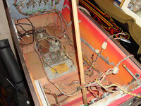
Oh! Not too bad. After untangling the rather strange wiring loom from the power cable it all looks pretty good. Much better than Paragon did. Looking a bit more closely the hacks start to worm their way out of the woodwork though:
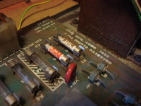
Domestic plug fuses! 13A in the +5VDC which should be 6A and 3A in the +43VDC solenoid supply which should be 5A. The actual values are utterly irrelevant though as they're completely the wrong type of fuse. Easier to fit than paper-clips or tin foil though...
Let's see what lurks inside...

Oh! Not too bad. After untangling the rather strange wiring loom from the power cable it all looks pretty good. Much better than Paragon did. Looking a bit more closely the hacks start to worm their way out of the woodwork though:
- Hand twisted earth cable to earth braid. That ain't gonna cut the current mustard when there's a short.
- Extra green wire up to playfield GI. Not thick enough for the current and what's up with the original?
- A few small connector blocks. Splicing accidentally severed wires?
- Diagnostic test button dangling on just one wire.
- Some slightly odd re-wiring from one of the GI TRIACs. Might explain the green wire if it's dead. These are obsolete and a bugger to get hold of.

Domestic plug fuses! 13A in the +5VDC which should be 6A and 3A in the +43VDC solenoid supply which should be 5A. The actual values are utterly irrelevant though as they're completely the wrong type of fuse. Easier to fit than paper-clips or tin foil though...
OoopsI was just watching (and rather enjoying) one of the very informative videos on YouTube that was linked at the end of mine when I noticed a name on the side of the multi-meter. I'm assuming this is you, @lukewells?
Nice work! Subscribed to your channel and watching more vids
Check it out at 3:21:
View attachment 10255
Last edited:
I've got your number now @lukewells! I've seen your kit and setup - I know who I'm going to pester with my endless technical questions 
You have to be so careful. Us YouTube nutters are everywhere...
You have to be so careful. Us YouTube nutters are everywhere...
Small update 'cos this stuff is just so exciting. Had 5 minutes to spare before a phone call at work... checked the 13A mains plug, grotty as ****. Polished the pins and fuse holder, and fitted 3A fuse. Not keen on the US flex - the cores are dark green, black and white. Will be changing that for some modern UK flex soon. Pulled the wrong fuses from the power supply and put a fast blow 5A 3AG in each. F1 for the +11.9VDC unregulated (which eventually becomes the +5VDC regulated for the MPU) should be 6A but I haven't got any of those, so 5A will have to do. Interestingly, both PARAGON and VECTOR specifiy a 4A fuse for this circuit, so I wonder what GOLD BALL has that requires a 50% increase in potential current? That aside, I plugged it in and flicked the switch. Bearing in mind the wiring loom is totally disconnected nothing went bang. Surprisingly the playfield GI lit up. I think this is because the attract mode flasher TRIAC has been bypassed.
Peter, do you know yet if it'll operate the gold ball randomly or as a skill feature? Apparently a service kit was issued to allow the latter option, consisting of a U2 Eprom, different playfield plastics and instruction cards. See Ipdb for details.
Haven't quite got that far @Jay Walker! I've got EPROMs, that much I know. They're labelled with the Bally ROM numbers, but until I get the whole thing back together I've no idea if they're vanilla or custom.
Biggest problem at the present might be the transformer. Looks as though it might be duff... got some odd voltages. Only just squeezing out 100V on the HV although I know that can be low when not under load. But I can't find any voltages at all on either the OA or OB outputs for the switched illumination (feature lamps). Going to have to unbolt the whole thing and get it on the bench.
Found another bad fuse: 15A in place of 8A in OA
Mmm... seem to have about 150VAC on OB. Sure it should be about 5.9! And there's leakage somewhere as I'm get a couple of volts AC on OB with it plugged into the mains but switched OFF. Pull the mains plug and it's back to zero. Not good. Not good at all 
Back to basics. When you're tracing a fault remove all the unknowns, which in this case is everything!
Simply pulled the entire transformer assembly out of the bottom of the cabinet (much better place for it than in the backbox like PARAGON). Disconnected all the sockets and started by testing the input and output windings on the transformer, looking at continuity and resistance. I'm no expert but generally windings on a transformer should register as a direct electrical connection with very little resistance. Basically it's just a ruddy great long piece of wire. In a transformer that's over-heated and/or melted it'll either go open circuit or the resistance won't be right, usually too high.
Here's a crop of the power supply schematic that shows just the input (J1) and output (J5) connectors on either side of the transformer. Unlike PARAGON this transformer has permanently connected wires fitted to chunky Molex power connector blocks instead of soldered lugs. I've modified the schematic to show the jumper wire configuration for 240VAC operation as the manual shows settings for US 115 VAC. To change the voltage on the PARAGON transformer you have to move jumpers between the soldered lugs. The arrangement used in GOLD BALL means that either 2 or 3 jumper wires are moved between the pins on the power connector J1. Quite neat!
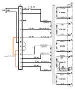
Well, with the test meter set for continuity/resistance testing I confirmed that all the windings look good. All were just a few Ohms resistance except the 170 VAC winding, which registered around 15 Ohms. Initially this alarmed me but I checked the same winding on PARAGON and that was 22 Ohms. I think this makes sense because I think the wire will be longer and thinner to get the relatively small step down from 240 to 170 VAC.
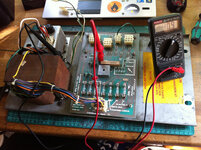
Next, it was time to plug it in. This was a little Heath Robinson as I didn't have any Molex pins spare, so just twisted and folded the bare ends of the live and neutral wires and poked them into pins 1 (live) and 5 (neutral) of connector J1. They were a surprisingly tight fit and I held the cable in place with some cable ties. The earth wire was stripped and clamped under one of the transformer mounting brackets:
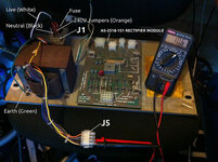
The photo shows the DMM set to the 200V AC range and connected to pins 9 and 10, which is one half of the 20V CT winding. I'm pretty sure CT stands for Centre Tapped as that's just what it is! I therefore assume half of 20VAC is 10VAC as that's what I'm seeing.
All the other voltages were roughly what they should have been, even under a no-load condition.
This doesn't prove the transformer is in 100% perfect working order but it's looking very favourable. Next step is to overhaul the AS-2518-151 RECTIFIER BOARD. I've already spotted that two of the diodes have been replaced in the 170 VAC HV section, so it's been worked on in the past. Might as well replace all four of these diodes, originally 1N4004, as I have loads of the higher current 1N4007 to hand. Just hope those Schottky fast recovery rectifier diodes are good as they're obsolete and then I'll have to source equivalents...
Simply pulled the entire transformer assembly out of the bottom of the cabinet (much better place for it than in the backbox like PARAGON). Disconnected all the sockets and started by testing the input and output windings on the transformer, looking at continuity and resistance. I'm no expert but generally windings on a transformer should register as a direct electrical connection with very little resistance. Basically it's just a ruddy great long piece of wire. In a transformer that's over-heated and/or melted it'll either go open circuit or the resistance won't be right, usually too high.
Here's a crop of the power supply schematic that shows just the input (J1) and output (J5) connectors on either side of the transformer. Unlike PARAGON this transformer has permanently connected wires fitted to chunky Molex power connector blocks instead of soldered lugs. I've modified the schematic to show the jumper wire configuration for 240VAC operation as the manual shows settings for US 115 VAC. To change the voltage on the PARAGON transformer you have to move jumpers between the soldered lugs. The arrangement used in GOLD BALL means that either 2 or 3 jumper wires are moved between the pins on the power connector J1. Quite neat!

Well, with the test meter set for continuity/resistance testing I confirmed that all the windings look good. All were just a few Ohms resistance except the 170 VAC winding, which registered around 15 Ohms. Initially this alarmed me but I checked the same winding on PARAGON and that was 22 Ohms. I think this makes sense because I think the wire will be longer and thinner to get the relatively small step down from 240 to 170 VAC.
Next, it was time to plug it in. This was a little Heath Robinson as I didn't have any Molex pins spare, so just twisted and folded the bare ends of the live and neutral wires and poked them into pins 1 (live) and 5 (neutral) of connector J1. They were a surprisingly tight fit and I held the cable in place with some cable ties. The earth wire was stripped and clamped under one of the transformer mounting brackets:

The photo shows the DMM set to the 200V AC range and connected to pins 9 and 10, which is one half of the 20V CT winding. I'm pretty sure CT stands for Centre Tapped as that's just what it is! I therefore assume half of 20VAC is 10VAC as that's what I'm seeing.
All the other voltages were roughly what they should have been, even under a no-load condition.
This doesn't prove the transformer is in 100% perfect working order but it's looking very favourable. Next step is to overhaul the AS-2518-151 RECTIFIER BOARD. I've already spotted that two of the diodes have been replaced in the 170 VAC HV section, so it's been worked on in the past. Might as well replace all four of these diodes, originally 1N4004, as I have loads of the higher current 1N4007 to hand. Just hope those Schottky fast recovery rectifier diodes are good as they're obsolete and then I'll have to source equivalents...
Last edited:
Spent a couple of hours yesterday day working on the PSU board in between making beds, hoovering, making breakfast, lunch and dinner, washing, gardening and playing MINECRAFT with my kids 
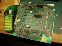
Here's the AS-2518-151 RECTIFIER BOARD is all its naked glory before I started:
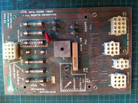
After pulling all the fuses I noticed the 0.75A Slow Blow for the HV had been incorrectly fitted with a Fast Acting 500mA. That's never going to help. There was also a 15A instead of 8A in one of the Feature Lamp circuits
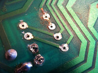
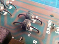
There were two pairs of different types of 1N4004 diodes CR1-4 in the HV (High Voltage) section, so someone has obviously done some work here before. The tracks on the underside are lifting a little, signs that they've been over-heated. For some reason it also looks as though someone tried to score through and cut two tracks. Note the solder bridge on the on the bottom-right pad and there was the same on the top-right pad before I sucked off the solder :
My OCD doesn't like non-matching parts, so I replaced CR1-4 with some higher rated 1N4007s:
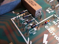
For anyone interested, these are the unusual, and now obsolete, Mr751 Schottky fast recovery high surge diodes that I was trying to find equivalent replacements for:
Everything else looked pretty good. I cleaned the board top and bottom with PCB flux cleaner, polished the fuse clips and slightly raised the 600Ω 10W power resistor to help a little with cooling. I then mounted it back on the chassis plate. I also clamped a short piece of earth wire to the chassis under the top-right screw and connected this to Pin 1 on connector J2 to reproduce the connection that is normally provided by the wiring loom (Pin 1 is just a run of green/yellow earth wire that runs back to the ground point on the line filter:
When I first tested the output voltages I got a few strange readings and then I remembered that some them have been rectified so need to switch the DMM from AC to DC!

Here's the AS-2518-151 RECTIFIER BOARD is all its naked glory before I started:

After pulling all the fuses I noticed the 0.75A Slow Blow for the HV had been incorrectly fitted with a Fast Acting 500mA. That's never going to help. There was also a 15A instead of 8A in one of the Feature Lamp circuits
There were two pairs of different types of 1N4004 diodes CR1-4 in the HV (High Voltage) section, so someone has obviously done some work here before. The tracks on the underside are lifting a little, signs that they've been over-heated. For some reason it also looks as though someone tried to score through and cut two tracks. Note the solder bridge on the on the bottom-right pad and there was the same on the top-right pad before I sucked off the solder :

My OCD doesn't like non-matching parts, so I replaced CR1-4 with some higher rated 1N4007s:

For anyone interested, these are the unusual, and now obsolete, Mr751 Schottky fast recovery high surge diodes that I was trying to find equivalent replacements for:

Everything else looked pretty good. I cleaned the board top and bottom with PCB flux cleaner, polished the fuse clips and slightly raised the 600Ω 10W power resistor to help a little with cooling. I then mounted it back on the chassis plate. I also clamped a short piece of earth wire to the chassis under the top-right screw and connected this to Pin 1 on connector J2 to reproduce the connection that is normally provided by the wiring loom (Pin 1 is just a run of green/yellow earth wire that runs back to the ground point on the line filter:

When I first tested the output voltages I got a few strange readings and then I remembered that some them have been rectified so need to switch the DMM from AC to DC!
- GI Reading: +6.90 VAC
+6.5 VAC unrectified for the playfield general illumination circuit. - GI Reading: +6.91 VAC
+6.5 VAC unrectified for the backbox general illumination circuit. - TP1 Reading: +177 VDC
Schematic says +230 VDC, but I think this always comes up low when there's no load. This ultimately supplies the +190 VDC for the displays. - TP2 ∅B Reading: +10.7 VAC
+10 VAC unrectified for the "FEATURE LIGHTS" a.k.a. switched illumination.
- TP3 ∅A Reading: +10.7 VAC
+10 VAC unrectified for the "FEATURE LIGHTS" a.k.a. switched illumination.
- TP4 Reading: +41.1 VDC
- +43 VDC for the solenoids.
- TP5 Reading: +12.18 VDC
+11.9 VDC. This is an unregulated output which is regulated to +5 VDC for the MPU.
Last edited:
Now that I'm happy that the A2 PSU MODULE is safe and working properly time to get it back into the cabinet. Whilst doing so I'm checking the wiring thoroughly as it's been hacked around a bit. For instance, I noticed the strip of earth braid that tees-off next to the EMI filter down to the PSU chassis wasn't actually connected!
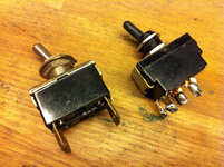
First to go was the sh*tty under-rated DPST on-off toggle switch. It was rated at 3A @ 125V and had a horrid switching action with tiddly lever. Move over and make way for a decent switch! Another nugget from the big box of ex-display parts from my days at Maplin, this one's rated for 10A @ 250V (left new 10A, right old 3A):
Safety cover cleaned and refitted:
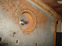
Rarely ever seen so here's the new switch poking out of its recess on the underside of the cabinet:
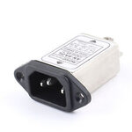
Next I turned my attention to refitting the mains cable back on the EMI filter. I'm going to ditch both the cable and EMI filter eventually. The cable because it's old, American and has the feckin' wrong colour wires. Bleurgh! And the EMI filter is going because I plan to fit IEC 320 C14 inlets with built in EMI filters:
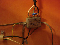
I was quite surprised by the little grey "tooth paste caps" used to splice the output wires of the EMI filter (you can see one connecting brown to black in the photo below). I assumed they were crimp-on covers but are actually screw on, with a sort of self-crimping action. They unscrew to expose the bare wires which have just been twisted together. Eek! How cheap. So I soldered the wires together and then fitted the caps. In the photo you can also see I clamped the vertical earth braid that runs to the PSU chassis under the left screw of the EMI. This pin is now at least two steps closer to passing a PAT inspection:
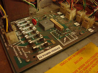
Then it was time to fit the A2 POWER MODULE. This is held in place with four excessively large bolts. The front two bolts are also used as the mounting points for the GI flasher TRIACs. It was also as this point that I started labelling everything using my trusty DYMO LetraTAG 2000. If you're tempted to get one of these don't buy the current LetraTag LT100-H. It's supposed to do the same job and although it has loads more fancy features (and uses less AA batteries) it fails miserably because it spits out at least 3 times as much blank space before and after the printed letters than the older LetraTAG 2000. This is a crap ploy by DYMO to make you use more tape.
The wiring in GOLD BALL is a total tangled mess and seems to have loads and loads of extra connectors, so labelling them all is going to be essential for me!
That's it for now, although I did discover why the backbox GI wasn't working the one time I switched everything on:
Never going to get very far with that! Bloody good job the two bare wires didn't touch...
First to go was the sh*tty under-rated DPST on-off toggle switch. It was rated at 3A @ 125V and had a horrid switching action with tiddly lever. Move over and make way for a decent switch! Another nugget from the big box of ex-display parts from my days at Maplin, this one's rated for 10A @ 250V (left new 10A, right old 3A):

Safety cover cleaned and refitted:

Rarely ever seen so here's the new switch poking out of its recess on the underside of the cabinet:

Next I turned my attention to refitting the mains cable back on the EMI filter. I'm going to ditch both the cable and EMI filter eventually. The cable because it's old, American and has the feckin' wrong colour wires. Bleurgh! And the EMI filter is going because I plan to fit IEC 320 C14 inlets with built in EMI filters:

I was quite surprised by the little grey "tooth paste caps" used to splice the output wires of the EMI filter (you can see one connecting brown to black in the photo below). I assumed they were crimp-on covers but are actually screw on, with a sort of self-crimping action. They unscrew to expose the bare wires which have just been twisted together. Eek! How cheap. So I soldered the wires together and then fitted the caps. In the photo you can also see I clamped the vertical earth braid that runs to the PSU chassis under the left screw of the EMI. This pin is now at least two steps closer to passing a PAT inspection:

Then it was time to fit the A2 POWER MODULE. This is held in place with four excessively large bolts. The front two bolts are also used as the mounting points for the GI flasher TRIACs. It was also as this point that I started labelling everything using my trusty DYMO LetraTAG 2000. If you're tempted to get one of these don't buy the current LetraTag LT100-H. It's supposed to do the same job and although it has loads more fancy features (and uses less AA batteries) it fails miserably because it spits out at least 3 times as much blank space before and after the printed letters than the older LetraTAG 2000. This is a crap ploy by DYMO to make you use more tape.
The wiring in GOLD BALL is a total tangled mess and seems to have loads and loads of extra connectors, so labelling them all is going to be essential for me!


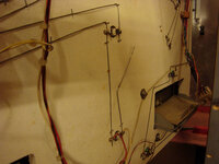
That's it for now, although I did discover why the backbox GI wasn't working the one time I switched everything on:

Never going to get very far with that! Bloody good job the two bare wires didn't touch...
Last edited:
OMG. Just started to have a poke around the HV LAMP / SOLENOID COMBO board and discovered another wrong fuse. Badly wrong.
Someone had fitted at 20mm T3.15A (that's T for time-delay or slow blow) instead of the correct, and admittedly expensive and hard to find, 1" 3/16A fast blow, often marked as F187mA.
Can they have mistakenly thought the 3,15A marking (comma instead of full-stop for the decimal point) was close enough to 3/16A? Board looks great. Really clean, all components look good, solder on the back neat. Fingers crossed it's good to go but wonder why it had lost the right fuse...
If there is one thing i've learnt from this place (and i've actually learnt loads of stuff) then it would be that you should ALWAYS check the fuse ratings on any machine you're receiving no matter who it came from. In my case R&B came from people on this very forum so I was really happy to find that all the fuses we properly rated.
Or so I thought.......
It was only when I stripped it down the other week to do the restore that I found the fuses on the bridge rectifiers were slightly over-rated. Not massively so - but naturally when I come to rebuild it i'll be putting the recommended fuses back in place. I think those two are easily overlooked as they're mounted between the large cap in the backbox and the rectifiers, there's also a fair bit of cabling which sits in front and could obscur them. I hadn't even noticed them until I came to start stripping things out of the backbox.
Last edited:
Nuts. Nuts. Nuts. 
Just plugged the MPU into the power supply and it isn't booting again! Assumed the PSU wasn't doing it's job but the +5VDC voltage was good. So pulled it out and put it back on the test bench. Still no joy. The test LED is back to being stuck on. Bugger. Checked the reset circuit - working perfectly. Exactly the same voltages as my other MPU board. All the chips check out as I swapped them with my other MPU and they all work in that.
That means there's still a duff intermittent component or far more likely dry joints and/or broken tracks.
Back to tracing tracks with the test meter...
The MPU is still giving me the ruddy run-around but I've bought a job-lot of Bally boards (6 MPUs, 5 Lamp Drivers, 3 Regulator/Solenoid Drivers, 1 Rectifer, 1 Sound Board plus some other boards) so hopefully I'll be able to cobble something together from that lot! Also included is an MPU Battery Corrosion Repair Kit that contains all the parts that get chuffed in the reset circuit. We shall see...
But in other news I've been working over the AS-2518-147 HV LAMP/SOLENOID COMBO BOARD that is unique to GOLD BALL and GRAND SLAM. As I was getting +230VDC it was almost inevitable that the transistors Q31, Q32 and Q33 in the +190 VDC REGULATOR section were toast. And they were. So much so they just registered as conducting connections. They even tripped my ESR meter into self-test mode which is done by joining inputs 1, 2 and 3 together! Also, without surprise R54 was frazzled to a non-conducting crisp too.
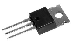
Q33 is a bugger because it's an obsolete T0-66 package 2N3584. There are some on eBay... for £18. Naff off! Farnell has them for £7 each (better) but the £12 postage is a killer on small orders (and CPC don't have them). Everything else is readily available and cheap. I may pull a Q33 off one of the other boards I'm getting but I've read up about using an equivalent BUX84 in it's place. Only issue with this is it requires slight modification of the heatsink as BUX84 is a TO-220 package (purists won't like it as it won't look right) but it's a more recent and far superior chip and should pretty much last forever. Best of all they only cost 79p. More details here: http://home.pacific.net.au/~jennyah/BUX84.htm
But meanwhile I took the time to re-draw the circuit diagram as the one in the schematic scan on IPDB.org is unreadable. I've been as careful as I can to ensure this is correct but I'm only human and there is always the possibility I've made an error. No warranty supplied or implied!
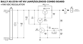
The circuit itself is no different to that on the more usual AS-2518-22 but all the part numbers are different as are the connector pin-outs.
But in other news I've been working over the AS-2518-147 HV LAMP/SOLENOID COMBO BOARD that is unique to GOLD BALL and GRAND SLAM. As I was getting +230VDC it was almost inevitable that the transistors Q31, Q32 and Q33 in the +190 VDC REGULATOR section were toast. And they were. So much so they just registered as conducting connections. They even tripped my ESR meter into self-test mode which is done by joining inputs 1, 2 and 3 together! Also, without surprise R54 was frazzled to a non-conducting crisp too.
Q33 is a bugger because it's an obsolete T0-66 package 2N3584. There are some on eBay... for £18. Naff off! Farnell has them for £7 each (better) but the £12 postage is a killer on small orders (and CPC don't have them). Everything else is readily available and cheap. I may pull a Q33 off one of the other boards I'm getting but I've read up about using an equivalent BUX84 in it's place. Only issue with this is it requires slight modification of the heatsink as BUX84 is a TO-220 package (purists won't like it as it won't look right) but it's a more recent and far superior chip and should pretty much last forever. Best of all they only cost 79p. More details here: http://home.pacific.net.au/~jennyah/BUX84.htm
But meanwhile I took the time to re-draw the circuit diagram as the one in the schematic scan on IPDB.org is unreadable. I've been as careful as I can to ensure this is correct but I'm only human and there is always the possibility I've made an error. No warranty supplied or implied!

The circuit itself is no different to that on the more usual AS-2518-22 but all the part numbers are different as are the connector pin-outs.
Spent a couple of hours last night stripping down the +190VDC regulator section on the combo board. And here is the AS-2518-147 HV LAMP / SOLENOID COMBO BOARD as used only in GOLD BALL and GRAND SLAM:
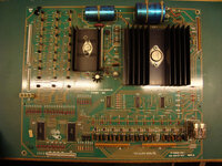
It's essentially the same +5VDC and +190VDC regulators for MPU and displays, with a reduced solenoid SCR section cut down from 19 to 11 SCRs (and one SCR Q41 isn't even fitted as it's not used on GB) and a slightly reduced lamp driver section with 30 circuits instead of 36 found on the more common A5 AS-2518-23 LAMP DRIVER BOARD.
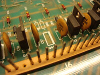
Looking over the +190VDC section I spot the first mistake:
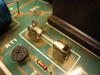
Yes, wrong fuse. Again. This time a 20mm 3.15A Slow Blow (T) where there should be a 3/16A 8AG Fast Blow (F). No wonder all the transistors are toast!
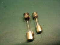
Correct fuse fitted having just removed the retaining nuts on the Q33 2N3584 BJT (Bipolar Junction Transistor) that sits in the middle of the large black heatsink. This component is utterly obsolete and superseded by more modern devices. Even the TO-66 package shape is obsolete. You can get NOS ones on eBay... for around £18 although Farnell has them for about £7. However, I'm going to attempt to use a better device, such as a BUX84 as suggested here, which only requires slight modification of the heatsink. The 25kΩ trimmer pot is just cheap rubbish. It goes open circuit at the ends of travel and the value jitters all over the place in between. It's got to go!
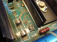
Transistors Q31 and Q32 (2N3440 - another bipolar power transistor) are also both toast, as was Q33. No surprise with a 3.15 fuse R54 was also toast, another common failure when the transistors fail. You can see it's dark brown in the middle.
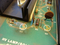
All the other components tested ok including the +140V Zener diode (as best as I could tell with a DMM). I'm still going to replace everything with new as they're all just a few pence each.
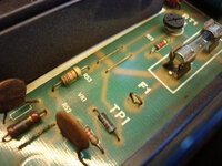
So, there we are. Stripped down and waiting for new components. Tracks on the back look good, nothing burnt.
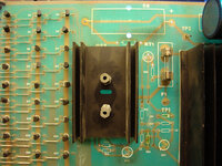


It's essentially the same +5VDC and +190VDC regulators for MPU and displays, with a reduced solenoid SCR section cut down from 19 to 11 SCRs (and one SCR Q41 isn't even fitted as it's not used on GB) and a slightly reduced lamp driver section with 30 circuits instead of 36 found on the more common A5 AS-2518-23 LAMP DRIVER BOARD.

Looking over the +190VDC section I spot the first mistake:

Yes, wrong fuse. Again. This time a 20mm 3.15A Slow Blow (T) where there should be a 3/16A 8AG Fast Blow (F). No wonder all the transistors are toast!

Correct fuse fitted having just removed the retaining nuts on the Q33 2N3584 BJT (Bipolar Junction Transistor) that sits in the middle of the large black heatsink. This component is utterly obsolete and superseded by more modern devices. Even the TO-66 package shape is obsolete. You can get NOS ones on eBay... for around £18 although Farnell has them for about £7. However, I'm going to attempt to use a better device, such as a BUX84 as suggested here, which only requires slight modification of the heatsink. The 25kΩ trimmer pot is just cheap rubbish. It goes open circuit at the ends of travel and the value jitters all over the place in between. It's got to go!

Transistors Q31 and Q32 (2N3440 - another bipolar power transistor) are also both toast, as was Q33. No surprise with a 3.15 fuse

All the other components tested ok including the +140V Zener diode (as best as I could tell with a DMM). I'm still going to replace everything with new as they're all just a few pence each.

So, there we are. Stripped down and waiting for new components. Tracks on the back look good, nothing burnt.


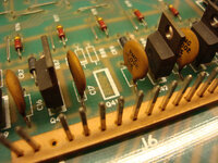
Looking at the track-side I've noticed one difference between this and the more common AS-2528-23 board: notice the two big screw heads (centre-right) both have tracks leading away from them? On the -23 board only the top one does. These are the mounting bolts and both are connected to the body of the 2N3583 which is the collector, but the -147 makes use of this to route the tracks in a different way, whereas the -23 has two tracks leading from the top bolt to different parts of the circuit - the bottom bolt is used only to hold the heatsink and device in place. This means if I do a conversion to a BUX84, which is in a 3-legged TO-220 package I'll have to find a neat way of joining the two mounting points together electrically.

Spent a couple of hours last night stripping down the +190VDC regulator section on the combo board. And here is the AS-2518-147 HV LAMP / SOLENOID COMBO BOARD as used only in GOLD BALL and GRAND SLAM:
It's essentially the same +5VDC and +190VDC regulators for MPU and displays, with a reduced solenoid SCR section cut down from 19 to 11 SCRs (and one SCR Q41 isn't even fitted as it's not used on GB) and a slightly reduced lamp driver section with 30 circuits instead of 36 found on the more common A5 AS-2518-23 LAMP DRIVER BOARD.
I thought at first sight that the missing darlington transistor had been pinched for use elsewhere, rather than never being fitted in the first place. But the associated diode and resistor are absent too. The regular Lamp Driver board has 60 SCR's, though ( a mixture of the 2N5060 type used here and the larger C106).
Yep, @Jay Walker, Q41 is definitely originally absent and schematics confirm it's not used. Your observations have prompted me to look more closely at the solenoid and lamp driver schematics! You're right about the circuits on the lamp driver - I had simply counted the SCRs that looked the same. There are no MCR106-1 SCRs on GOLD BALL, unlike the 24 on a AS-2518-23 LAMP DRIVER BOARD. Looking at the schematics for my PARAGON there doesn't seem to be any pattern to their usage? Some playfield spots are lit by MCR106-1s whilst adjacent ones are lit by the smaller 2N5060s.
The 2N5060s are 0.8A and the MCR106-1s are 4A, so it looks like Bally had mind to create a bank of 36 general purpose switched lamps and a bank of 24 higher-power switched lamps. Guess they decided this was a bit of a waste?
And on the AS-2518-22 SOLENOID BOARD there are 19 SCRs but even on the behemoth that is PARAGON only 14 are used. Guess they decided this was a waste too hence the creation of the combined HV / LAMP / SOLENOID board with fewer circuits, e.g., just 11 solenoid SCRs.
I wonder if this significant drop in switched illumination is why in GOLD BALL they added the TRIACs to flash the GI when in attract mode? Bascially, the GI temporarily becomes switched GI albeit just being flashed on and off automatically, but then reverts to fixed GI during gameplay. Wow those guys were getting desperate back in 1983 to squeeze every last cent from the bottom line...
Just out of curiosity, were the 8 solenoid circuits that were dropped all 'momentary' outputs, or a mixture of momentary and continuous? I'd expect the two coils for the special outhole gate arrangement to be on continuous driver ouputs; if so the flipper relay and coin lockout (if there is one) would mean all four of the continuous outputs were needed.
Last edited:


