What's new
Pinball info

Register a free account today to become a member! Once signed in, you'll be able to participate on this site by adding your own topics and posts, as well as connect with other members through your own private inbox!

In Progress 1976 Moon Flight

JT.

Site Supporter
Joined
Jul 24, 2011
Messages
2,962
Location
North West UK
I've fancied having a go at restoring an EM for a while now, and recently picked up a 1976 Zaccaria Moon Flight, which is ideal for the project that I wanted. Here's a list of the problems I've found so far (I've not 100% decided whether I'll tackle all of these or not yet):

- There are a lot of dings to the cabinet, as you might expect from a 38 year old machine.
- The left side of the case has split into three parts. Not sure if this is repairable or whether a new panel will be needed.
- The right side of the cabinet is not so bad, just a few scrapes.
- The rear of the case has seen better days and will need replacing.
- The bits of wood around the top which the backbox slots onto have seen better days.
- The backbox has a few chunks of wood missing.
- The translite is in quite nice condition. It has a couple of scrapes but hopefully these are fixable.
- The playfield is in great condition for the age. there are a few small areas of wear. I've not decided whether to try and fix these or just leave as is yet.
- I can see a couple of the rollover switches have broken and will need repairing or replacing.
- The legs are pitted with rust and will need sorting.
- The coin door is in quite nice condition, maybe a good clean will do to fix that up. Similarly the shooter handle.
- The metal components around the top of the glass need cleaning/rust removal.
- It needs leg bolts, back box bolts, and a new power cable / power socket.

....and that 's it so far. I've yet to look under the playfield as the keys have gone walk about. So I'll be breaking the lock at some point soon to have a look underneath - no doubt plenty to do under there - if nothing else, a very good clean and polish of everything.

Here's some pics:

The rear side of the translite - just a couple of small scratches to address, but generally very nice.
DSCF0509.JPG

Front of the translite, overall looks pretty good
DSCF0510.JPG


Close up of the scratch on the translite, hopefully repairable
DSCF0511.JPG

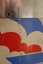
Rear of the case: seen far better days!
DSCF0512.JPG

Will need a new power socket, this one is badly damaged
DSCF0514.JPG

A close up of that rear panel damage.
DSCF0515.JPG

The left side of the case: the panel has split into three bits. Looks like it's made of mdf too, which was a surprise for me. The webbing in the paint might be tricky to achieve if I decide to repaint.
DSCF0516.JPG

The centre bit comes away, so I can glimpse inside.
DSCF0517.JPG

The bit that the backbox slots onto came away in my hand when moving it, so that'll need replacing.
DSCF0519.JPG

The playfield is in great condition for the age.
DSCF0521.JPG

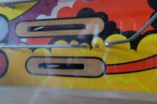
Just small bits of wear around some inserts
DSCF0522.JPG

Not sure whether I'll try and fix this or just leave it.
DSCF0523.JPG

A bit of wear to sort out here
DSCF0527.JPG

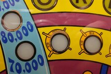
A bit of the "1000! has worn off on this popbumper which will need sorting.
DSCF0528.JPG

The coin door and shooter are OK, maybe just needs a good clean.
DSCF0529.JPG

The right side of the case is comparatively OK, a few scrapes and a bit of structural damage towards the rear.
DSCF0531.JPG

The backbox needs a bit of work on these dinks.
DSCF0535.JPG

And these ones too....
DSCF0536.JPG

This side too...
DSCF0537.JPG

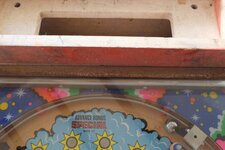
And the top of the backbox could do with sorting as well.
DSCF0538.JPG

The legs are rusty, so will need sorting.
DSCF0540.JPG

A close up of the leg rust. They're all like this.
DSCF0542.JPG

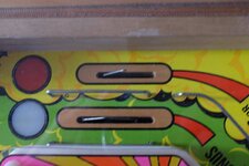
A couple of these bits of wire that stick out through the playfield on top of switches have snapped.
DSCF0549.JPG

And this one too...
DSCF0550.JPG


So that's about it for now. I need to get the case opened and have a look inside, then decide what to tackle first!
 

Attachments

  • DSCF0524.JPG
    DSCF0524.JPG
    84.7 KB · Views: 5
  • DSCF0525.JPG
    DSCF0525.JPG
    69.9 KB · Views: 5
  • DSCF0526.JPG
    DSCF0526.JPG
    88.3 KB · Views: 5
  • DSCF0532.JPG
    DSCF0532.JPG
    43.3 KB · Views: 6
  • DSCF0533.JPG
    DSCF0533.JPG
    88.5 KB · Views: 5
  • Like
Reactions: JT.
What happens when you turn it on?

Thanks for those links @ronsplooter.

That's a good question about turning it on, one I've yet to address :) Hopefully no fireworks! It didn't come with a power cable for the three pin (knackered) socket on the back, so it's not been plugged in yet. Incidentally,the socket has no earth wire attached - does that sound right, did they not earth these old machines?
 
Re. the broken roll-over wires; if they're both outlane switches, they may have always been like that. The ones on U.S. built games (without outlane kick-back, etc,) were, until the speed of play saw balls sometimes travelling up the sloping sides of the card holder and then up the outlane, when 2-way wireforms appeared in outlanes. F'r instance, Williams F-14 has 2-way w/forms on both outlanes; obviously for the kick-back on the left side, but I've seen a ball fly up the right hand outlane, as above.

The slots in the playfield are shorter, too, so a full-length wireform may not fit. The 'broken' end of the l/h one does look ragged, though.
 
Last edited:
  • Like
Reactions: JT.
I need to get the case opened and have a look inside, then decide what to tackle first!

Prepare to be frightened...

I opened the bottom of my Ski Jump, Nope nothing for me here and closed it again. I might open it again soon though, maybe
 
  • Like
Reactions: JT.
No Earth was standard.
Replace with a 3 cord flex. Check Live and Neutral BEFORE you cut the lead as it's normal to have two black wires.
Best to run some earth cable to all exposed metal parts, inside the cabinet of course. Coin door and side rails especially.
Story time...Had a discussion with an owner recently who said that it had passed it's PAT test and the sticker proved it. I said it would as the tester would give a high resistance between Live and Earth. He didn't check there was an earth path from the plug to the exposed metal parts.
So why Earth? If you don't, I'll wager that one day you'll feel a tingling when your playing. Check voltage from the un-earthed EM to another machine and you will see anything up to 100Vac. I know, it happened to me!
Meantime, use a plug in RCD just for that machine as this will detect any small voltage on the Neutral. (But earth machine too)
Dave
 
Re. the broken roll-over wires; if they're both outlane switches, they may have always been like that. U.S. built games (without outlane kick-back, etc,) were, until the speed of play saw balls sometimes travelling up the sloping sides of the card holder and then up the outlane, when 2-way wireforms appeared in outlanes.

Cheers Jay, looking again, I think you're right
 
Polish up the legs with kitchen foil and coke - they should come up nicely :)
 
  • Like
Reactions: JT.
Cool! Really looking forward to reading a few EM shop logs. Been very tempted by an EM. This one, with it's spacey theme, would have been perfect. Looks like you've landed on your feet with that playfield. Looks in great condition in total contrast to the cabinet which looks as though most of it is heading for a life as kindling :eek: Still, easier to fix woodwork that find ancient unique EM parts.

GOOD LUCK!
Zaccaria playfields are bulletproof. Never seen a poor one. It's like they were made to survive reentry from space [emoji3] I don't know what they did different but shame the other manufacturers of the time didn't do the same.
 
Zaccaria playfields are bulletproof. Never seen a poor one. It's like they were made to survive reentry from space [emoji3] I don't know what they did different but shame the other manufacturers of the time didn't do the same.
Wasnt it something to do with the lead paint???
 
The wireforms are not snapped, that's normal :)

No earth is normal on these (but it sound definitely have one added)

The split lines on the left look really clean, so I'd say that gluing and clamping it would be far easier than replacing and painting

The back piece is history and needs replacing


I bet if you plug it in, the GI lights will come on and it will sit in game over.

I also bet you can probably start a game after a couple of tries, and then it will eventually get stuck decremented the ball counter stepper :)
 
I managed to get it opened - the dodgy board in the middle on the right of the cabinet can be completely removed - making a handy entrance point to take the lock apart from the inside :) I also found what look like 40 year old schematics inside it, which was good.

I managed to get it plugged in - it lights up and the score motor just keeps turning, so now trying to follow the schematics :)
 
Spot on! Just been working on a 1968 Williams Cue T. Endless games as the stepper on the ball count has stopped working. An endless game on a EM is no fun, it's like a re-occurring nightmare!
 
I wonder what they "varnished" the playfield with? Whatever it is it's got to be better than the water-soluble "Diamond Plate" cr@p Bally used (or whatever it's called - I'm sure my PARAGON says diamond on it somewhere). Shockingly useless stuff. Not only is it not diamond hard at all, you can pretty much rub it off with a wet cloth. Not such a good idea. Both of my Bally project pins have obvious water damage where liquid has somehow entered the top of the playfied (ventilation grill in the neck?) and run down leaving an area of severe planking, stripped varnish and paint flaking.
 
I managed to get it opened - the dodgy board in the middle on the right of the cabinet can be completely removed - making a handy entrance point to take the lock apart from the inside :) I also found what look like 40 year old schematics inside it, which was good.

I managed to get it plugged in - it lights up and the score motor just keeps turning, so now trying to follow the schematics :)

If you poke around at the switches on the score motor it will start usually, so something is out of adjustment on there. The main thing to note is check the ball count stepper in the back box, when it gets stuck in an endless loop, its usually the decrement coil has fired, but it has stuck on and not releasing (I think one of the switches on the score motor is normally closed and should open to release the coil - but it often doesn't) when the coil is stuck on, it will get hot, so don't leave it running like that for a long time :)
 
  • Like
Reactions: JT.
That got it Luke - so we now have flippers, and a load of other stuff happening. The start button doesn't seem to have any effect though (e.g. ball doesn't get kicked out) and there's an intermittent tilt light coming on every so often. Also one of the score wheels doesn't turn, but it has a different coloured coil compared to all the others, so maybe there's an issue there to sort too :)

EDIT: OK, so there's no problem with that score reel, that's now working fine - I hadn't pressed the right buttons to trigger it. And I worked out that to kick out a ball you need to press the flipper buttons, rather than the credit button. And I just blocked the tilt mechanisms for now to resolve that temporarily.

EDIT 2: OK: so sometimes pressing the flipper buttons kicks a ball out, and sometimes not. So something seems not quite right there. But managed to have a couple of games on it :)
 
Last edited:
Right, time for some inside photos. I've started taking it all apart to get ready for cleaning. Nothing too horrifying inside it at first check - well, maybe the fuses a little non-standard.

Powersupply and chimer unit just to the side out of focus.
DSCF0554.jpg

A few connectors that allow all the gubbins to be removed from inside the case without using a soldering iron.
DSCF0555.jpg

Inside of coin door
DSCF0558.jpg

Some of the relays
DSCF0561.jpg


More relays - everything inside the case was factory marked up (most of it legibly too!). Not on the underside of the playfield though, there you have to work out what everything is.
DSCF0563.jpg

The replay counter
DSCF0578.jpg

Some score wheels
DSCF0579.jpg


The underside of the playfield, ready for cleaning.
DSCF0581.jpg

The majority of the stuff from inside the case comes out simply by undoing two screws and lifting this bit of plywood out.
DSCF0582.jpg

A bit more case damage is now visible.
DSCF0583.jpg

A lot of dirt!
DSCF0584.jpg


Not sure about these fuses - most are the right amperage
DSCF0586.jpg

So that's it for inside photos for now. Next I'll start cleaning some stuff.
 
I don't know about EMs but I suspect that domestic mains fuses are not the right type regardless of rating. Probably need fast blows. Also, as they're too short there isn't sufficient contact area with the fuse clip. This can cause a burn out because the current is flowing through a smaller area. Clean and replace!
 
I don't know about EMs but I suspect that domestic mains fuses are not the right type regardless of rating. Probably need fast blows. Also, as they're too short there isn't sufficient contact area with the fuse clip. This can cause a burn out because the current is flowing through a smaller area. Clean and replace!

Yup, I placed an order with Andy for a few bits earlier on, and new fuses were on the list :)
 
So, having taken everything out of the case, tonight's little job was removing the side rails...and these things are a bitch to remove. I tried several techniques - starting off more refined and gradually resorting to force.

My first attempt was to try and pull the twist nails out using pliers, but there was no hope as they were very tightly in place and corroded. Then I tried drilling them, but my drill bits weren't sharp enough. Then I tried sawing a groove in the dome-head of the nails with a junior hacksaw, but it just polished the surface of the nails rather than cutting a groove....So eventually I opted for using a paint removal tool to prise the side of the rail up, bringing the nails out with it. This worked very well for the ones at the bottom of the rail, but for the ones at the top, I needed to use a screwdriver (underneath the paint stripper) to spread the load. It was then just a matter of hammering the corroded nails out of their holes from the underside.

So overall this technique was very successful - it did cause a tiny bit of damage to the case where the top nails were removed, but nothing that a bit of filler won't resolve. And, far more importantly, the side rails were totally undamaged by this process :)

Lifting the nails along the lower edge was easy.
IMAG0550.jpg

But the ones at the top of the rail needed a different technique.
IMAG0554.jpg

But eventually they both came off, with all the nails corroded in place. But it easy enough to hammer these out.
IMAG0555.jpg
 
Oh yeah, and two new toys arrived today :)

First up a tumbler and a load of corn cob grains - there's plenty on this pin to keep this busy..
IMAG0557.jpg


And second up, a tool for cutting mylar, which I'll be using to make a stencil for repainting the cabinet. To be honest, the art on the Moon Flight is not that complex and it might have been possible to make the entire stencil using a craft knife, but there are a few curved bits, so hopefully this will help get a better finish.
IMAG0558.jpg
 
Good work,

Have you decided whether to earth the machine? If so, you'll need an earth for the side rails. While they're removed would be the ideal time to make a small square hole in each, for suitable dome-headed coach-bolts. These would pass through the woodwork to connect with the earth braid run around the inside of the cabinet.
 
  • Like
Reactions: JT.
Good work,

Have you decided whether to earth the machine? If so, you'll need an earth for the side rails. While they're removed would be the ideal time to make a small square hole in each, for suitable dome-headed coach-bolts. These would pass through the woodwork to connect with the earth braid run around the inside of the cabinet.

I've not decided yet @Jay Walker, although if I do it, I'd want to do it in such a way as it was not visible from the outside of the cab.
 
Today's job has been to get a few playfield parts removed and into the tumbler, then trying out a few techniques for re-painting the cab. I started by trying to use a thin mylar sheet to create a template, through which I could then spray paint. It turns out that there are a couple of problems with this approach: firstly, it's incredibly hard to cut smooth curves into the mylar, even using the stencil cutting tool pictured a couple of posts up; and, second, when you spray through the template, you get a lot of 'overspray' around the edges (the one good thing about this is that it covers up any imperfections in the template cutting). On a lot of older machines, overspray is desirable as that is how they were painted originally, but I've just discovered that Zaccarias were screen printed :mad:, hence why the painting on the Moon Flight has nice crisp edges.

So I'm ditching the template method for now and trying a different technique. For this I'm using air-brush 'frisket film' which is a very thin film with low tack adhesive on one side, which seems much better for getting those sharp edges I'm looking for. So now I just have to decide, do I apply a sheet of frisket, cut out all the bits to make a template, then remove it, clean up the cabinet (sand, undercoat, etc) then reapply the frisket and then paint - the downside of this is that I'll need to remove and store the sticky frisket whilst the cab is being prepared. Or do I make a stencil drawing of the art on tracing paper, clean up the cabinet, then apply the sticky frisket, put the tracing paper stencil on top of it, and then cut through the stencil and the frisket together, then, finally, paint it. More effort for the second approach, and the step with traced stencil might introduce a degree of inaccuracy in the final artwork, but removing and storing the cut frisket in the first option might be tricky. Not decided yet...:hmm:


Here's a pic of the 'overspray' - it's the dots you can see near the edges (don't pay too much attention to the wobbly edges, that's just bleed because the board I sprayed wasn't treated).
DSCF0628.jpg
 
Last edited:
@JT. I used frisket film for part of my FG cab resto...trust me you don't want to have to remove it and store it, it'll be a massively ball ache. It doesn't come off as easy as you think and it'll be really hard if not impossible to retain it's shape. Tracing it out sounds like a better option to me :)

Not sure what I'm going to do about mine yet as I don't have any original art to work from so might try and make some card stencils based on my own approximation of the Moon Flight art...will have to break out the pencils and do some drawing :D
 
  • Like
Reactions: JT.
Back
Top Bottom