The Zener Diode Regulator
Zener Diodes can be used to produce a stabilised voltage output with low ripple under varying load current conditions. By passing a small current through the diode from a voltage source, via a suitable current limiting resistor (RS), the zener diode will conduct sufficient current to maintain a voltage drop of Vout.
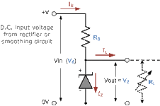
We remember from the previous tutorials that the DC output voltage from the half or full-wave rectifiers contains ripple superimposed onto the DC voltage and that as the load value changes so to does the average output voltage. By connecting a simple zener stabiliser circuit as shown below across the output of the rectifier, a more stable output voltage can be produced.
Zener Diode Regulator

The resistor, RS is connected in series with the zener diode to limit the current flow through the diode with the voltage source, VS being connected across the combination. The stabilised output voltage Vout is taken from across the zener diode. The zener diode is connected with its cathode terminal connected to the positive rail of the DC supply so it is reverse biased and will be operating in its breakdown condition. Resistor RS is selected so to limit the maximum current flowing in the circuit.
With no load connected to the circuit, the load current will be zero, ( IL = 0 ), and all the circuit current passes through the zener diode which in turn dissipates its maximum power. Also a small value of the series resistor RS will result in a greater diode current when the load resistance RL is connected and large as this will increase the power dissipation requirement of the diode so care must be taken when selecting the appropriate value of series resistance so that the zener’s maximum power rating is not exceeded under this no-load or high-impedance condition.
The load is connected in parallel with the zener diode, so the voltage across RL is always the same as the zener voltage, ( VR = VZ ). There is a minimum zener current for which the stabilization of the voltage is effective and the zener current must stay above this value operating under load within its breakdown region at all times. The upper limit of current is of course dependant upon the power rating of the device. The supply voltage VS must be greater than VZ.
One small problem with zener diode stabiliser circuits is that the diode can sometimes generate electrical noise on top of the DC supply as it tries to stabilise the voltage. Normally this is not a problem for most applications but the addition of a large value decoupling capacitor across the zener’s output may be required to give additional smoothing.
Then to summarise a little. A zener diode is always operated in its reverse biased condition. A voltage regulator circuit can be designed using a zener diode to maintain a constant DC output voltage across the load in spite of variations in the input voltage or changes in the load current. The zener voltage regulator consists of a current limiting resistor RS connected in series with the input voltage VS with the zener diode connected in parallel with the load RL in this reverse biased condition. The stabilized output voltage is always selected to be the same as the breakdown voltageVZ of the diode.


