What's new
Pinball info

Register a free account today to become a member! Once signed in, you'll be able to participate on this site by adding your own topics and posts, as well as connect with other members through your own private inbox!

WPC Lamp Matrix to Arduino

Nutty

Site Supporter
Joined
Oct 13, 2017
Messages
251
Location
Dorset
I want to use an opto isolator on the lamp matrix. I have a Getaway and I want to interface the traffic lights Red Amber Green to 3 inputs on an Arduino

I am looking for suggestions of a simple circuit using using 3 x 4n25
 
Last edited:
Without giving a full life story :) I have lost touch a bit with electronics, when I was 14 in the 80`s I built circuits like a Z80 PIO on my ZX Spectrum to run 240v Disco Lights & a Fruit machine 50v Payout coil with triacs no problem but that was 35 years ago. Moved in repairing domestic appliances and now I run a computer business so component out / in.

I have the kit electronics microscope. inspection Lamp etc. I can read circuit diagrams, just working out the values of the components needed will be my problem. I am thinking there will be an issue because the lamp matrix strobes.

I am about to test a 4n25 on the Getaway Mars Lamp as I want a signal from that but that seems easier as it is driven by 24v DC.
 
Sounds like a lot more than me!

I don’t know if those lamps are 6v or 12v. Best to check. Looks like the option coupler is 3V?

Anyway - after you’ve looped off the connector on the board (bit of simple crumpling), you need some kind of isolation and then voltage reduction?

Sounds like you’d have the knowledge for that.

Hope not to hijack your post - but Another theory maybe worth looking at (could be miles off here), is intercepting the command from the CPU to light those lamps. Maybe a bit of custom ribbon cable between the 2 boards and then onto your Arduino.

Just a theory, I don’t even know the protocol, baud rates, etc of how the boards communicate. Would give lots more scope for cool modding of your machine if it can be done.

Anyone with knowledge of data lines and specs of communication would be a key contributor to this one.

Or keep it simple with your original idea!
Cheers

Mike
 
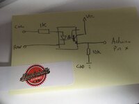
Arduino's can read the wpc matrix just fine. Using an opto isolator is the perfect way. As the data received will be from a matrix though you will need to write a program to decode the signals into something more meaningful. ie a lamp that is ON will not just be a logical high, it will be a series of high bits.

A simple diagram to follow for getting data off a wpc lamp matrix is:

IMG_5517.JPG
 
Thanks for that so having an 6v AC LED in parallel with the opto isolator will not upset the matrix ?
I I have one of @Paul anti flicker rooms.
I did think the output would not be a steady high, so when the lamp is off would the status be a steady low because the 10k resistor is pulling it low ?
 
Thanks for that so having an 6v AC LED in parallel with the opto isolator will not upset the matrix ?
I I have one of @Paul anti flicker rooms.
I did think the output would not be a steady high, so when the lamp is off would the status be a steady low because the 10k resistor is pulling it low ?

I think you need to explain what you are trying to do. You don't want anything adding on the pinballs matrix side. Whatever you want to 'drive' from the information gathered in 'reading' the matrix would be driven from an output on the arduino, possibly using a basic transistor setup.
 
ok so I have a Getaway and I have made some 2812 Led Bumber caps. The caps will be doing there own colour and pattern with the Ardunio etc when the traffic light is all out but when the Green traffic light is on I want the caps to turn Green, Traffic light to Amber ... Caps to Amber and so on.
 
What you are saying @myPinballs is the opto isolator should be the only item on the matrix the Arduino will have to drive the original traffic lights as well as the bumper caps ?
 
Last edited:
What you ar saying is the opto isolator should be the only item on the matrix the Arduino will have to drive the original traffic lights as well as the bumper caps ?

No, the opto isolator allows you to read what the bulb is receiving signal wise without having the 18v pulse going to a logic input. You can leave the pinball as it is. I misunderstood what you were saying when you said '6v ac led bulbs in parallel' as i thought you were adding extra bulbs directly on the matrix.

So, the diagram i drew for you shows you how to connect up each bulb from the traffic lights. Then you need to write some code on the arduino that will need to decide what an 'on' lamp is as opposed to an off one. The diagram will input a logic 0 to the arduino when the lamp is not being pulsed and a logic 1 when it is pulsed on the matrix. REMEMBER though, an on lamp to the eye as its a matrix will still receive a certain number of logical 0 inputs so your code needs to handle this.

I could provide code that already does all this for you, but that wont be free.
 
Back
Top Bottom