Dear all, a question my Dad has asked for me to pass on. Any help appreciated.
I have a WPC CPU which is confusing me.
There are 4 switches that are not working - all in Row 4
Everything else on the CPU works exactly as expected.
(I have swopped in another CPU, so I know the error is on the board
and not in the wiring or the plugs etc)
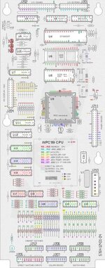
One of the bad switches is on PIN 4 on J209,
which goes to Pin 4 on J208 and then....
D6 1N4004
R58 470 ohm 1/4w
R57 68 ohm 1/4w
U18A LM339
R27 4.7K ohm 1/4w
U13B 74LS240
As far as I can tell by comparing readings with IC's on the good CPU
there is no issue (when testing on component legs) or with any of the resistors etc
so I think (if the components above are indeed the correct ones) then it
perhaps is an issue with the Trace at some point- as there is some historic acid damage, which has been neutralised.
Please can someone confirm that pin 4 goes through the components identified and I presume I should get continuity directly between pin4 and a leg of R27
With my meter on Diode test, Black lead on Pin 4 and Red lead on the left leg of R27 I get a reading of 1.862 - which I would think is pretty encouraging in terms of connectivity - yet still not working.
Although U18 appears to test good, perhaps the pins which deal with Row 4 switches are not passing the correct data.
Any help appreciated. Thank you.
I have a WPC CPU which is confusing me.
There are 4 switches that are not working - all in Row 4
Everything else on the CPU works exactly as expected.
(I have swopped in another CPU, so I know the error is on the board
and not in the wiring or the plugs etc)
One of the bad switches is on PIN 4 on J209,
which goes to Pin 4 on J208 and then....
D6 1N4004
R58 470 ohm 1/4w
R57 68 ohm 1/4w
U18A LM339
R27 4.7K ohm 1/4w
U13B 74LS240
As far as I can tell by comparing readings with IC's on the good CPU
there is no issue (when testing on component legs) or with any of the resistors etc
so I think (if the components above are indeed the correct ones) then it
perhaps is an issue with the Trace at some point- as there is some historic acid damage, which has been neutralised.
Please can someone confirm that pin 4 goes through the components identified and I presume I should get continuity directly between pin4 and a leg of R27
With my meter on Diode test, Black lead on Pin 4 and Red lead on the left leg of R27 I get a reading of 1.862 - which I would think is pretty encouraging in terms of connectivity - yet still not working.
Although U18 appears to test good, perhaps the pins which deal with Row 4 switches are not passing the correct data.
Any help appreciated. Thank you.
 My Dad also sends his regards to you and Gail.