What's new
Pinball info

Register a free account today to become a member! Once signed in, you'll be able to participate on this site by adding your own topics and posts, as well as connect with other members through your own private inbox!

Vertical Lines on DMD - Data East Batman

bjones371

Registered
Joined
Jan 3, 2016
Messages
11
Location
Manchester, UK
Hi All,

I picked up a Data East Batman a few weeks ago which had some vertical lines permanently illuminated on the DMD, probably every 6 or so, see image here:
s8.postimg.org_rrilgyrzp_IMG_20151226_183216.jpg
Yesterday, during play, the number increased, and now every other line is illuminated, like so:
s10.postimg.org_uh345zxzd_IMG_20160102_WA0009.jpg

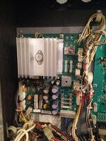
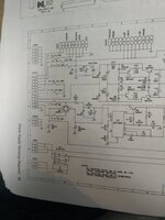
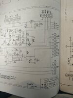
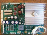
I've done some prodding with a multimeter and have a feeling that the issue is being caused by a faulty DM7407N IC that sends to the data in on the HV5408 which is connected the DMD itself from what I can work out. I measure a fluctuating voltage across R21, and no voltage whatsoever across R22 (I've replaced R22 but the issue persists).

Can anyone suggest any/all of the following please:
  • What I should do next in terms of diagnostics to confirm which component is faulty.
  • Any suggestions of UK based repairers that would be able to help if it's beyond my capability?
  • Where I might be able to get hold of a replacement DMD if it comes to that (they're proving rare!)
If uploads of any schematics/diagrams from the manual will help anyone out then I can provide, I have hard copies I can scan in.

Thanks in advance!
Ben
 
I ended up buying a pinled for my st25 to replace the dead one, not sure you will find a plasma one these days, but hope you get that one sorted
 
I ended up buying a pinled for my st25 to replace the dead one, not sure you will find a plasma one these days, but hope you get that one sorted
I thought of that first off and also Dr Pinball's DMD Extender, sadly Dr Pinball isn't compatible with 128x16 size, and pinled are sold out of the 128x16s at the minute, I'm keeping an eye on the website though :)
 
I got mine from Andy at pinballmania during the summer, not sure if he has more, or what about pin palace?
 
Mine was £180 had no other option really, not sure if mine was out gassed but was dead as a door nail, voltages were good
 
I had exactly this problem on my wpc Shadow, with those vertical lines per your first picture - but they never got any worse. It was periodic, but always seemed to happen after I moved the game/ removed the head to get in a different room/ redecalled the head so had stripped and rebuilt it

I just checked connectors\ reflowed solder\ cleaned pins (very fine wet and dry paper to polish them rather than scratch them followed by ispropyl alcohol to remove residue) and I also put tiny round files into the molex connectors to clean them too, then I flushed them out with isopropyl alcohol as best I could. I have a desoldering tool and it came with tiny round files, basically wires the thickness of pinball gate wire with rough ends, to enable you to clean out the metal tube that the solder gets sucked into. This did the trick for me
 
Cheers for the tips @DRD - a fuse blew this afternoon and typically it was the one which drives the DMD, so diagnostics are on hold until the replacements arrive tomorrow or Wednesday. Once they're here I'll give your suggestions a try if I can find some of the tiny files, or make something similar!
 
Tried swapping a fuse in today and it blew straight away... Luckily Farnell had a minimum order qty of 10, so I disconnected the DMD and plugged a new fuse in, and that immediately blew too. The fuse blowing is F7, which is a 0.5A S-B type 313. According to the schematic it sits between pin 7 of CN1X12 and ground. Since the DMD has been disconnected and the issue still exists, does that suggest a problem somewhere on the power supply board, and if so where do I start with that one?

Thanks!
 
Probably one of the high volts transistors or zener diodes in the hv easy to test if they are short with a meter, maybe post up some pics and you can be guided what to check

Ronnie
 
I've attached a photo of the supply board and the schematic to this post, had to split that in to two to make it readable.
 

Attachments

  • IMG_20160107_145626.jpg
    IMG_20160107_145626.jpg
    112.6 KB · Views: 12
  • IMG_20160107_145857.jpg
    IMG_20160107_145857.jpg
    80.4 KB · Views: 11
  • IMG_20160107_145910.jpg
    IMG_20160107_145910.jpg
    84.8 KB · Views: 10
Check the 2 transistors for shorts and the cap for bloating or leaks all circled red and the diodes in the 2 x areas although I think the cap may be in the 5v but it's prone to fail
 

Attachments

  • 100-1202.JPG
    100-1202.JPG
    70.9 KB · Views: 15
Check the 2 transistors for shorts and the cap for bloating or leaks all circled red and the diodes in the 2 x areas although I think the cap may be in the 5v but it's prone to fail

Cap C7 looks a tad fat but you're right in that it's in the 5V. TR3 tests OK from my limited knowledge but am getting zero resistance between all pins on TR4, so I'm guessing it's safe to say that's where the fault lies? It's an MJE350 according to the schematic.
 
Replaced TR4 which is no longer shorting across pins, the pre driver tested OK - once I'd got the power supply board out (screws were hard work!) I was able to get to the other components properly and looks like D10 has also failed, as D8 and D7 show a forward voltage of 0.529 but D10 is showing 0. Powered the board back up and while it's not blowing fuses any more I'm still not seeing -110v at the connector for the DMD driver, D10 does sit between TR4 and the ground so makes sense that would be the next component that's failed.

Now to try and find a 1N5379B diode that is stocked somewhere in the UK :hmm: cheers for all your help so far!

EDIT: Got some on the way - good old eBay.
 
Last edited:
Batman is same boards and DMD as my Hook. If I can help with any readings or such like from my machine let me know.
 
Now that diode rings a bell when I repaired mine, I'm sure I used 2 diodes to make up the correct forward voltage as could not find the correct value like you. let me see if I can find any details ..........
 
is it the diode mentioned below?

so I opted for BZx85C 100v in series with another one of 10v?
 
That is nice adding the Zener voltages in series, do you need to check the total Wattage is equivalent too? 1N5379B is 5W I can't see many others at that level.
 
That is nice adding the Zener voltages in series, do you need to check the total Wattage is equivalent too? 1N5379B is 5W I can't see many others at that level.


I'm not sure but what I did worked and gave the correct voltages, I got advice from someone who knows just can't remember who
 
Sorry for the radio silence, and thanks again for the help I've replaced D10 and have life back in the screen. Unfortunately the vertical lines are very much still present! I'm going to have a rummage with a logic probe and see what I can work out this afternoon about what is stuck high and whether it's coming from the CPU or the DMD circuitry, and I'll try the pin cleanup suggested by @DRD when I get some fine enough paper and contact cleaner.
 
Ok here's what I've found:
  • Pin 27 (Data In) on U13 (driver chip for even columns) is constantly high (11.27V)
  • Pin 27 (Data In) on U14 (driver chip for odd columns) fluctuates at around 3-5V, I assume as the display instruction changes.
  • Pin 10 on U5 (connects to pin 27 on U13) is constantly high (11.27V)
  • Pin 11 on U5 is constantly 1.87V
  • Pin 12 on U5 (connects to pin 27 on U14) fluctuates from 3 to 4.5V.
  • Pin 13 on U5 fluctuates from 1.7V to 2.1V.
  • Pin 7 on U10 (connects to pin 11 on U5) is constantly 1.9V
  • Pins 3-6 on U10 (supply info to pin 7 on U10) fluctuate at various voltages.
  • Pin 9 on U10 connects to pin 13 on U5) fluctuates from 1.7 to 2.4V.
  • Pins 10-13 on U10 (supply info to pin 9 on U10) fluctuate at various voltages.
The above is me working backward from each column driver following the same path until I spot a difference. Since the states on pins 3-6 is the same as the states on pins 10-13 on U10, but the states on output pins 7 and 9 are different, that leads me to thinking the HC153 chip in U10 is causing the lines. Does that sound reasonable? If it is, that's one of the chips behind the DMD glass, and so will be very difficult/impossible to replace :(
 
Hey folks,

An update on this one, I replaced U10 this evening, and there is not a vertical line in sight! The soldering wasn't the easiest job in the world but was worth sticking with. Spent a total of about £40 on this, including a new soldering iron, so saved a few quid off the cost of a replacement.

Cheers everyone for the help on this.

B
 
  • Like
Reactions: DRD
Back
Top Bottom