What's new
Pinball info

Register a free account today to become a member! Once signed in, you'll be able to participate on this site by adding your own topics and posts, as well as connect with other members through your own private inbox!

TZ - G.I. doesn't dim (FIXED)

Stupid question.. do I put the probes on the diode pins or the solder pads where they are connected to the PCB, or shouldn't it matter?

As said I was struggling to get readings with several diodes that I randomly tested, so I think I'm just doing it wrong.

I don't feel confident in saying one way or the other whether D3 or indeed any other diode is bad, or even just slightly bad. At least with the fuses I could get consistent, repeatable results. With the exception of the GI not dimming (somewhat academic with LEDs fitted anyway) everything in the game works perfectly, so clearly all these diodes I'm failing to get readings on aren't defective.

I really appreciate all the help you're trying to give. I do think however that I need someone to come out and probably tell me in 10 minutes decisively what's wrong with the GI. I don't even know what I'm looking for with these traces, for example.
 
Yup I shouldn't have mentioned the unconnected cables, didn't mean to confuse the issue.
 
Pin off.

DMM on continuity test. Put one probe (red or black doesn't matter) on the start point of the trace and the other on the end point. If you have continuity, you will hear a buzz sound. If not the trace is broken somewhere (mostly at the solder pads).

Test also the 2 diodes. Red and black at both ends. In one way you should read nothing on the DMM. Then switch both probes and you should read something from 0,4-0,6.
Ok picking this back up again as I'm keen to get my LED and GI OCD boards fitted to my TZ.

I put my DMM on continuity test and put one probe on anode D3 and the other on anode D38, basically exactly where the arrows point in this image. The DMM buzzes and reads around 0.03 or something (from memory). Does that mean the trace(s) from BR2 are ok?

Is the next step to test zero crossing using TP4? I think I know where TP4 is, but not sure where I need to put the other probe.

I'm keen to get someone out to ascertain that the power driver board is actually faulty before I take it out and ship it off somewhere, as I've read that it could possibly be the CPU board and/or the ASIC that is at fault instead. Anyone around the south west (Bath area) with an oscilloscope who can be tempted with bacon sandwiches, beer, etc? :)
 
When is the GI supposed to dim on TZ? I remember playing with this option in the menu on mine and wondering what it was as it never seemed to do anything.
 
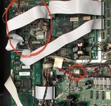
For what it's worth I took some photos in case anything obvious stands out.

View attachment 65600

Probably not related but there is Battery acid green on the pad of R198, the dull pads of R199, C1, R204, C12, R205 show that they're being attacked as well. C1 and C12 look like resistors so best test them for their value before replacing them.
 
Missed all these updates for some reason, didn't get a thread notification :(

Thanks for heads up about those acid marks. The batteries have been completely off board for some time, prior to my ownership, so I guess that would predate those marks. Isn't it a bit odd for acid damage to be on the power board, not the CPU board where the batteries would be located?

For what it's worth everything works on the game with the exception of the G.I. dimming, but will get it looked at regardless - so thanks for pointing it out.
 
Last edited:
Thought I’d resurrect this as the last couple of days I’ve been fitting the LED and GI OCD boards I bought for TZ.

The maker of the board - herg - suggested that GI dimming might work in spite of my Zero Cross signal from the PDB being potentially knackered, because of how and where it gets the signal, etc.

Well, it doesn’t work, if anything it’s very weird and I can’t really blame it on The Twilight Zone itself.

What I’ve noticed is as follows:
  • With default WPC89 settings, String 3 (“Clock and Insert”) does not illuminate at all.
  • String 3 is set to Input 3 (like the others are set to their corresponding number)
  • Changing String 3 to another input, or “Always On” makes it illuminate.
  • When playing with Manual Mode in the GI OCD tool I can manually dim each individual string (as in the lights dim to whatever brightness I specify as expected)
  • When set to Game Mode (normal) all GI is at full brightness at all times.
  • The GI test menu does nothing - all GI is at max brightness at all times, even when testing only one string (this is different to how it was before installing the board - the individual strings wouldn’t dim but they would switch off when not being tested). I other words testing “Playfield Left” at any dim level = all GI is at full brightness.
I’m a bit perplexed by the String 3 strangeness, as it isn’t explained by the Zero Cross problem I think my Power Driver Board has. Has anyone got their GI OCD settings for TZ and can confirm what it looks like?

Guess I need to look into getting my ZC fixed now, as the LED OCD is working and looks awesome. :(
 
Anyone? :(

Also, looking to buy a replacement Power Driver Board as it probably makes sense to have a spare.

Looking in the backbox on my TZ my PDB has the flipper relay (I think!) which I think makes it a A-12697-1 instead of A-12697-3, but I also appear to have the Fliptronics board?

5D18347B-6EDA-4AE6-BEDD-6CB083253F01.jpeg

Thoughts? Which version should I be looking to buy?
 
Anyone? :(

Also, looking to buy a replacement Power Driver Board as it probably makes sense to have a spare.

Looking in the backbox on my TZ my PDB has the flipper relay (I think!) which I think makes it a A-12697-1 instead of A-12697-3, but I also appear to have the Fliptronics board?

View attachment 99147

Thoughts? Which version should I be looking to buy?

send me your driver board ( and cpu) and I’ll check them over for you. The zero cross circuit doesn’t fail that often. It can be an issue with the asic on the cpu board to.

you dont need to buy a new power driver board
 
Just to draw a line under this... there was a leaking capacitor which had interfered with the ZC circuit. Cap replaced, Power Board reinstalled and I have fully functioning dimming. Yay!

(The oddity with String 3/Input 3 went away after the repair too)

It really is not fun removing the Power Board, so many wires that get in the way, and try to sneak under the board when you’re trying to get it back on the screws. :(
 
Back
Top Bottom