What's new
Pinball info

Register a free account today to become a member! Once signed in, you'll be able to participate on this site by adding your own topics and posts, as well as connect with other members through your own private inbox!

Top Insert GI out on T2

OK it was bugging me.

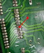
The schematic I had was correct. Pin 1 and 7 and f110 are on the same brown circuit.

Where you have marked f110 is actually f106. F110 is to the left on your pic and it looks like you have cracking on the far left fuse clip of f110 in your pic and the right fuse clip liiks to have very little solder. I would reflow both but it will be the one with cracking on the left that is causing the issue.
 
Thanks for your continued efforts at daft o'clock in the morning.

Reflowed solder on the fuse clips and these are the results (lights still out)

- J120-1 to J120-7 is around 2.2vac.
- J120-6 to J120-11 is 6.7vac.
- J120-11 to F106 is 0 on both sides of the fuse.
- F106 has continuity.

So effectively... no change :-(

EDIT: I've just found out something by accident. If I place my multimeter probe (or any metal object) in between J120-7 and J120-8 - the seemingly broken lights on the backbox come on instantly... as soon as I remove it, they go off.

Obviously it's creating a connection.

What in the hell does this mean though? Is this good or bad?
 
Last edited:
EDIT: I've just found out something by accident. If I place my multimeter probe (or any metal object) in between J120-7 and J120-8 - the seemingly broken lights on the backbox come on instantly... as soon as I remove it, they go off.

What you are doing here is bridging the power from pin 8 to pin 7 so the brown circuit is just getting its power from the orange circuit. It proves there is no issue with the lamps and wiring to the upper gi on the insert panel. It also proves that you have a continuity issue on the board or in the wire from the transformer to the board. There is not much in that part of the circuit:

J115-3 to f110 to j120-7 to j121-7.

The tests you have done has narrowed it down to a continuity issue between f110 and j120-7 and as the trace is on the component side of the board you may not be able to see the issue as it is under the components (the fuse clip or pin j120-7.

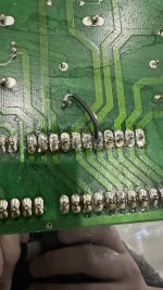
Easiest fix is to solder a jumper wire between f110 and pin j120-7 on the solder side of the board.
 
Aha, understood. I'll see if I can find some spare wire, and if so give this a go tomorrow and report back.

Thank you again Paul!!!
 
IMG_0431.jpeg

Done. Plugged in, tested, all working again. Great.

Switched off, plugged rest of connectors in and now game won't boot, and no lights are on.

Think I need to give it a couple of hours and come back to it.
 
If nothing is coming on then check the main fuses in both plug and just inside coin door. Also check F110 to see if blown. Maybe your jumper is in contact with metal ground sheet in backbox - jumpers need to be as flat as possible on the board to prevent. And check all connectors are correctly installed - if necessary pull them all and plug them in in stages.
 
You likely just misaligned the ribbon cables by one pin.
It was this... but guess which ribbon cable. The one going from my DMD to the DMD board.

If I unplug it, everything comes to life. As soon as I plug it in, everything goes off.

Good God
 
It was this... but guess which ribbon cable. The one going from my DMD to the DMD board.

If I unplug it, everything comes to life. As soon as I plug it in, everything goes off.

Good God

Could be you have it in reverse, or the ribbon cable is kinked.

Thankfully ribbon cables are cheap, if its not playing ball. Just replace it. :D
 
I've tried another ribbon cable, no difference. Have referred back to previous photos and it's round the correct way.

Anyway, after a good look round, I had J112 misaligned by one pin.

All working now! Thanks all and thanks to @Asiapinball especially for his brilliant deduction techniques!
 
Back
Top Bottom