What's new
Pinball info

Register a free account today to become a member! Once signed in, you'll be able to participate on this site by adding your own topics and posts, as well as connect with other members through your own private inbox!

Top Insert GI out on T2

Dinsdale

Site Supporter
Joined
Oct 19, 2022
Messages
318
Location
UK
Ok, I've been sitting on this for a week because I wanted to troubleshoot it myself.

My top inset GI is out on the backbox.

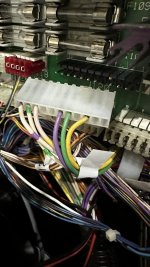
First thing I did was wiggle J120 connector, and voila. The lights come back on until pressure is taken off.

So I suspected a cracked solder joint. I've reflowed the solder but it's still the same, but I have noticed it took a bit more wiggling. So I reflowed solder again. While I'm not an expert I did think I did an Ok job. Everything else still worked.

To verify I did an ok job, I got the multimeter out and there was continuity between all the pins of J120 and the corresponding pins of J121.

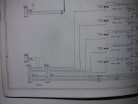
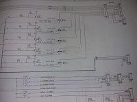
So looking at the manual, top insert GI is J120-7 on White/Brown. Firstly, I suspect the manual is wrong because the sides going up to this area are White/Violet. If anyone can verify this if nothing else, it will save me barking up the wrong tree.

It also says the transistor is Q18. This seems ok with multimeter checking continuity with the legs but I can't imagine it's transitor related if power comes on with a wiggle?

Its a new make and female connector so not sure how I can check if that is good (I haven't got the crimping tools)

Any ideas welcome, or tell me if I'm barking up the wrong tree.

EDIT: Have also swapped the connectors at J120 and J121. Wiggling brings power back so confident female connectors are good.

Could it just be bad solder even if I have continuity on the pins (front and back)?
 
Last edited:
If you have swapped j120 and j121 and problem is still in backbox it's not the board it's the connectors.
 
Strip back 10mm from the wires of the faulty gi circuit and reinsert using your idc tool.
The Molex tool doesn't fit on these newer connectors. I wonder if there's a hairline crack in one of the pins as you suggest.
 

Attachments

  • IMG_0403.jpeg
    IMG_0403.jpeg
    101.8 KB · Views: 13
Pull one of the connectors and check voltage between pin 1 and pin 7 of j120 or j121. Should be 6.3vac.
 
Are you getting 6.3vac between pin 2 and pin 8
Just managed to check properly with more time. 6.5vac on pin 2 and 8 on J120's pins.

Maybe it is the connector. It's Molex but I may replace with IDC as I've got the tool to punch down for IDC.
 
But if there is not 6.5vac between pin 1 and pin 7 on the board the fault is in the board not the connector. Check between pin 1 and pin 7 again for 6.5vac now we know for sure that you got your dmm set up right for measuring 6vac as you did it correct between pin 2 and 8. I was expecting you to get a 6.5vac reading between pin 2 and pin 8 as you dont have problems with that gi string.
 
OK so the fault is on the board or in the yellow and white wiring from the transformer to the board.

Try between pin 1 and fuse f110. See if you get 6.5vac or 2.3vac. Take readings at both ends of the fuse.
 
6.9/7.0vac on pin 1 to F110. I'm not convinced the manual is correct here though!

Also I am going to invest in a better multimeter. This one is temperamental when changing the dial. I've got to press it right in most times.
 
OK so fuse is good but you have an issue with the trace between f110 and pin 7.
 

Attachments

  • 17023357140951398166049510050962.jpg
    17023357140951398166049510050962.jpg
    95.9 KB · Views: 4
Thank you! Board will come off tomorrow and I'll take a look and post some pictures.

Great narrowing down, Paul - forever in your debt.
 
Thanks. I do have one query though. The manual has F110 as the White/Brown circuit... but the wires that are out are White/Violet.

Is this just a simple case of the manual being wrong? (I know from Pinside the T2 manual has been known to have some errors).
 
Thes pic you took shows brown circuit on pins 1 and 7 counting from the right. It all looks correctly wired in the pic. The gi circuits on wpc are always brown orange yellow green voilet reading from right to left I.e backwards from pin 1 on the right. Just as you have them in the pic.

Are you sure it's the voilet string that is out? If it is you need to be doing the tests between pins 6 and 11. And then between fuse 106 and pin11.

But you seem to have proved you also have an issue on the brown circuit.

It's hard diagnosing from a distance.
 
Manuals do have errors yes.
But these boards are the same in many many games.
It is very rare that it is anything more than bad tracks/connectors/pins.
Also worth checking the connector where the incoming cables come in on the left hand side (the vertical one on the botton left).
It is common to have to change these pins and connector as well. Check these for broken pins/tracks.
 
The manual is incorrect as it states that backbox insert gi is on brown and green lines but it is clear from Gary's pic that they are on brown and orange circuit.

Gary trace the brown circuit from the connector and see if it goes to the top insert gi. Maybe they changed the wire colour to violet after the first connection on the insert panel?
 
Last edited:
Also worth checking the connector where the incoming cables come in on the left hand side (the vertical one on the botton left).
Definitely worth checking J103. I had a similar issue with GI recently and it was this, wires were burned and only just clinging on. I moved the connector back a few mm onto good wire to fix.


IMG_0280.jpeg
 
Last edited:
That's connector j115 in the pic not j103. J115 supplies the ac for the gi.

J115 and its pins should not be the issue as Gary was getting 6.5vac between f110 and pin1. If there was an issue at j115 then he wouldn't have got this reading as j115 and its corresponding connectors are within the circuitry tested during this test.

The test between pin 1 and pin 7 introduces a little more circuitry into the testing and this is where the voltage reading drops so should be where the circuitry issue is.
 
Sorry, just got round to looking at this (one of those days)

IMG_0416.jpeg
Below is an image of the lights that are out. It is the White/Violet wires.

- J120-1 to J120-7 is around 2.5vac.
- J120-6 to J120-11 is 6.7vac.
- J120-11 to F106 is 0 on both sides of the fuse.
- F106 has continuity.

So do I have two issues? Here's a pic of the board with F110 and pin 1 and 11 marked for reference.

IMG_0419.jpeg
 
It looks like the schematic I have has the fuses labelled incorrectly. It is late now so I will take a look in the morning.

Your violet circuit looks fine as you are getting the correct voltage. There appears to be an issue on the brown circuit on the board.

It's hard to tell the colour of the wires on the backbox insert from your pic but I found a video that showed it was brown and orange circuits on the backbox insert panel. Looking at your connectors at j120 and j121 I expect yours is same as brown and orange are on one connector for the backbox and the 3 others are on the other connector.

So you seem to have a single fault in the board on the brown circuit which we know is not working as you only get 2.3vac across pins 1 and 7.
 
Back
Top Bottom