What's new
Pinball info

Register a free account today to become a member! Once signed in, you'll be able to participate on this site by adding your own topics and posts, as well as connect with other members through your own private inbox!

Stern Driver Board woes

Arv

Registered
Joined
Jul 21, 2011
Messages
3,399
Alias
.
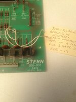
So i've re-pinned the connectors on the TA-100 all showing correct voltages. I can't seem to get the 5v on the SDU-100 Rev C.

- Re-pinned connectors J3 and J4
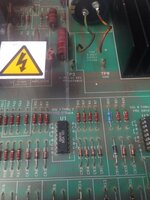
- Rebuilt 5v section (apart from 2.2 Cap)
- New Voltage Regulator (tested on bench)
- Ground mods done and 5v TP1 -> Tp3

Now i can give the board 12v on the bench and all is well, but as soon as i plug it into the backbox no 5v, i've checked pin 12 on J3 and its giving out 12v unreg.

Any ideas?
 
12v with reference to the cabinet ground or a ground on the board. ?

If the ground connection is poor then the 12v is floating on the board.
 
Grounds on the board. The 190v is there as is the 240v.
 
So i've re-pinned the connectors on the TA-100 all showing correct voltages. I can't seem to get the 5v on the SDU-100 Rev C.

- Re-pinned connectors J3 and J4
- Rebuilt 5v section (apart from 2.2 Cap)
- New Voltage Regulator (tested on bench)
- Ground mods done and 5v TP1 -> Tp3

Now i can give the board 12v on the bench and all is well, but as soon as i plug it into the backbox no 5v, i've checked pin 12 on J3 and its giving out 12v unreg.

Any ideas?
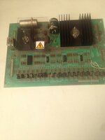

What else is plugged into the 5v line in the game? possible short somewhere or large current draw pulling the driver board down? If you have another game or board worth a quick check to quickly rule out board or game issue etc.

After that disconnect any board installed and using 5v to see if can be isolated
 
Nothing else is plugged in just the driver board, it's got me puzzled.
 
What's the 5v reading at the test points ? is it totally 0v, or + some smaller amount? Does it change the reading if you take the ground from the boards ground or the earth braid point in the backbox?
 
Reads 0v, I've had the board out resting on a newspaper plugged in still the same.
 
I've not tried disconnecting the earth braid yet, I'll give that a go.
 
If the board tests good on the bench using a seperate 12 v feed and the games wiring is ok then you are only left with the 12v feed from the games rectifier board . I’d double check this area. What’s the unregulated 12v reading? 16v or lower?
 
Yeah around 16v. I've re-done all 3 BRs on the TA-100.

All tests are good from the rectifier board.

I've changed the cap now to a new 2.2uf.

I'm getting 0.7v now at TP5 (12v) but still 0.0v on the 5v.
 
Sorted it there was a jumper missing off the TA-100 board according to the schematics.
 
Having sorted the SDU board out and the game now booting i can start a game, but all is not well dear reader.

All switches are registering in test, only problem i have now is the Solenoids don't seem to be working correctly, i.e If the Right slingshot is hit the knocker sounds and the right bumper will trigger the ball trough.

I've had the logic probe on U2 (74154), according to the schematic pins 19,20,21,22 and 23 are the inputs. I'm thinking faulty chip?
 
Hello, Arv,

Seawitch has the Stern convention of each solenoid 'test' number being the driver transistor number, e.g. the knocker, Solenoid 3, drives from Q3. The revision 'F' circuit board also shown in this thread has screening which shows what inputs on the data lines should switch each momentary solenoid transistor, Q's 1 to 14, and Q 16. If the right pattern is on the inputs for a particular solenoid, but a different transistor is switched, then I do think faulty de-coder
 
Pin 23 is the only one thats not pulsing. These early Stern's are a fricking pita.
 
Replaced U2, still the same problem.

So I re-pinned J4 on the MPU all is well once more. A fully functional Seawitch.
 
Back
Top Bottom