What's new
Pinball info

Register a free account today to become a member! Once signed in, you'll be able to participate on this site by adding your own topics and posts, as well as connect with other members through your own private inbox!

Pin2DMDXL woes

Sgt GrizZ

Registered
Joined
Jul 21, 2011
Messages
11,336
Location
Ex PinballInfo Admin . MIA Brighton Hove beach
Alias
Ive
Surfs up and its fvcked ! :rolleyes:

Have a Pin2dmdXL in Baywatch.

The display started freezing the other day and then reverted to the Pin2DMD Logo screen where it stayed.

It then went completely blank / dead. I have since found the power connector on the display is flaky. Pressing on it power is retored. I need to repin it I think. For now its holding again.

Anyway - still have the other issue. On power on it just halts at the Logo screen. I can get into the menu by pressing the buttons. fiddled about but doesn't seem to have changed anything.

I have tried swapping ribbon cables around - no joy.
Took MicroSD card out - same thing except Red LED lights on the board with card out ?? I'm not sure what the LEDs indicate. The blue one is not lit .... I thought this should be flashing ???? But could be wrong.


Any guidance appreciated.

Is @MadNat still around with any words of Pin2dmd wisdom ?

 
Hi there,

Staying on the Pin2DMD logo could indicate that it is not receiving data from the machine. The blue LED on the back of the Pin2DMD indicates that it is communicating with the machine and receiving data.

Sega XL machines are notorious for bad 5V on the display board as well as display boards playing up over time. Your ribbon cables could also affect the signal, but I would start by checking the voltage on the smaller DMD Display board that sits behind your DMD. It likes dead on or close to 5V. If it is low you may be getting the lack of signal. Reseat your ribbon cables as well. There is a service bulletin from sega regarding a fix/mod to get a more stable 5V signal off your board.

You can also do an input test in the Pin2DMD menu. You will need to ground each pin (one row only) while in the test menu, each should register as closed besides 1 I believe (1,3,5,7,11) as you ground them. Obviously the ribbon cable needs to be disconnected from the Pin2DMD to try this.

The Red LED can indicate a few things, but generally in your case it is telling you there is no SD car present. It will also stay solid when you are in the settings menu.

I've also had some flaky DMD boards, as well as having to reseat eproms etc and connectors. Lot's of things to look for but I would start with the voltage, then do the input test.

Update: A few additions
 
Last edited:
Hi there,

Staying on the Pin2DMD logo could indicate that it is not receiving data from the machine. The blue LED on the back of the Pin2DMD indicates that it is communicating with the machine and receiving data.

Sega XL machines are notorious for bad 5V on the display board as well as display boards playing up over time. Your ribbon cables could also affect the signal, but I would start by checking the voltage on the smaller DMD Display board that sits behind your DMD. It likes dead on or close to 5V. If it is low you may be getting the lack of signal. Reseat your ribbon cables as well. There is a service bulletin from sega regarding a fix/mod to get a more stable 5V signal off your board.

You can also do an input test in the Pin2DMD menu. You will need to ground each pin (one row only) while in the test menu, each should register and closed besides 1 I believe as you ground them. Obviously the ribbon cable needs to be disconnected from the Pin2DMD to try this.

The Red LED can indicate a few things, but generally in your case it is telling you there is no SD car present. It will also stay solid when you are in the settings menu.

Thanks for the speedy reply.

Yeah - aware of the 5v issue. I have the service bulletin wiring mod but I still only get about 4.8v at the Display board and at the Pin2DMD. That said its usually been pretty stable. Have had the odd reset in the past.

This is the first time it has been stuck like this so not sure what has changed.
 
Yeah - aware of the 5v issue. I have the service bulletin wiring mod but I still only get about 4.8v at the Display board and at the Pin2DMD. That said its usually been pretty stable. Have had the odd reset in the past.

IMO, 4.8V is probably too low and many other factors can affect it as well. If you're getting a low 5V from your mod, I would actually check the board it is connected to as that may also need a service. But before you do, you could try the input test to make sure that you're getting a signal, and possibly update the firmware as well here (copy the updated file to your SD card and let it boot and update, it will go black and reset).

The SD card not being attached won't make much difference as that holds the colour file mainly. You can try and reset the Pin2DMD settings which is in the config menu, right near the end of options, make sure to save the config too, do this with the SD card in, as it may have separate settings and these won't save if you put the card back in. It may default to Virtual Pin which has an auto detect, if this doesn't work, go back in and change it to Sega to be sure, then save.

Edit: Just to confirm, the firmware linked is for the EVO board, if you have a different model you will need a different firmware version. This can be found here for the Nucleo or old custom firmware
 
Last edited:
IMO, 4.8V is probably too low and many other factors can affect it as well. If you're getting a low 5V from your mod, I would actually check the board it is connected to as that may also need a service. But before you do, you could try the input test to make sure that you're getting a signal, and possibly update the firmware as well here (copy the updated file to your SD card and let it boot and update, it will go black and reset).

The SD card not being attached won't make much difference as that holds the colour file mainly. You can try and reset the Pin2DMD settings which is in the config menu, right near the end of options, make sure to save the config too, do this with the SD card in, as it may have separate settings and these won't save if you put the card back in. It may default to Virtual Pin which has an auto detect, if this doesn't work, go back in and change it to Sega to be sure, then save.

Edit: Just to confirm, the firmware linked is for the EVO board, if you have a different model you will need a different firmware version. This can be found here for the Nucleo or old custom firmware

Yeah - the main power supply is throwing out less than 5v to begin with. I just haven't ever addressed it as its been pretty stable. I should do though :rolleyes:

I'll try the other suggestions . Thanks. - might be the weekend before I have time now.
 
My first Baywatch, which used to be @robotgreg’s one had an independent switching power supply solely for the display.
 
I hear ya man. I have a feeling mine is following suite so following this eagerly hoping you sort it so I can copy 😝
 
All good advice from @Terranigma,

If you still have the original DMD stick that in and see if it work - that will tell you if there are issues with the ribbon cables or power.
If that display works - I would certainly recommend an input test on the PIN2DMD as suggested. There is an IC from the input that stabilises one of the signals (pins 9), that can fail… so testing if all others are working will help.

Voltage I’d be less concerned about - the integrated Buck converter on the board will take 12v and generate about 4.8v on on B/W machines and the processor runs fine (it actually operates on 3.3v) - my guess is you have a data issue.

Potentially the IC I mentioned has failed - but only an input test will confirm that for you.

Hope it helps.

Cheers
Mike
 
Last edited:
If you still have the original DMD stick that in and see if it work - that will tell you if there are issues with the ribbon cables or power.
If that display works - I would certainly recommend an input test on the PIN2DMD as suggested. There is an IC from the input that stabilises one of the signals (pins 9), that can fail… so testing if all others are working will help.
Good point, would be certainly be a good way to test if you still have the original.

Voltage I’d be less concerned about - the integrated Buck converter on the board will take 12v and generate about 4.8v on on B/W machines and the processor runs fine (it actually operates on 3.3v) - my guess is you have a data issue.
I agree with the voltage for the display, you're mainly worried about the amps in this case when they get super bright (that's one of the reasons why it's not recommended to run off a WPC/95 original HV connector). But the 5v in question is to do with the DMD Driver PCB that sits behind the display, that is the board that is super fussy with voltage. If that doesn't function correctly you won't get anything on any display. I haven't looked at the schematics to see if this shares the same source pcb from the backbox, but I believe the voltage for the Sega XL is taken from the 20-24V pin so should be no worries there in terms of voltage. Ofcourse will depend on what model you are using as well.
 
The XL should not be taken off the 5v on any game. I always fit external PSU's - they are dirt cheap.

Have you tried connecting a 5a 12v PSU to the screw terminals on the back and isolated that?

If you bought this off a legit business then shouldnt you return it to them under warranty?
If it was me I would fit a 10A 5V switch mode PSU. Run the DMD PCB board (on the back of the display) and the Pin2DMDXL. I would also common up the 0v on this power supply to the 0v in the backbox. As you said those DMD PCB boards are very fussy.
 
Good point, would be certainly be a good way to test if you still have the original.


I agree with the voltage for the display, you're mainly worried about the amps in this case when they get super bright (that's one of the reasons why it's not recommended to run off a WPC/95 original HV connector). But the 5v in question is to do with the DMD Driver PCB that sits behind the display, that is the board that is super fussy with voltage. If that doesn't function correctly you won't get anything on any display. I haven't looked at the schematics to see if this shares the same source pcb from the backbox, but I believe the voltage for the Sega XL is taken from the 20-24V pin so should be no worries there in terms of voltage. Ofcourse will depend on what model you are using as well.
My experience/thoughts - If the voltage/amps were an issue the logo screen would not function/display on the panels. You’d see issues on the panels before having a processor/data problem - which is what appears to be the case - with logo screen and no data being received/processed. My money is a failed IC1 if the input test works.

Let’s see.
Then if purchased via someone - send it back!
 
I’m assuming he bought it via one of the group buys Phil… a few XL’s were built and I remember someone telling me it was for a Baywatch.
 
My experience/thoughts - If the voltage/amps were an issue the logo screen would not function/display on the panels. You’d see issues on the panels before having a processor/data problem - which is what appears to be the case - with logo screen and no data being received/processed. My money is a failed IC1 if the input test works.
While he had a separate issue with possibly a loose connection or damaged power connector on his Pin2DMD beforehand, getting the logo on the screen means nothing in regards to the data. Staying on the logo screen on the other hand can indicate points of failure on the display, cables, driver pcb etc.

We are talking about a few separate points of possible failure here. Some related but some independent possibly.

First is the 5V that is going direct to the DMD Driver PCB which could be low and causing the PCB to fail sending a signal (or the physical power connector, or the ribbon cables). For Data East x16 (on board), x32 and also x64 they all have the display rom on the display PCB as well as the circuit to run the display data. There are various issues you can get when you have a bad DMD Driver PCB for Data East/Sega/Stern WS. First is just a blank screen, you would see the Pin2DMD logo at boot, then it would just go blank, usually but not always with a blue LED indicator flashing or solid at the back of the Pin2DMD. If it doesn't get that far it can get stuck on the Display version which is reading the Display Driver PCB rom but not going any further, while this could be ram, the CPU etc or even dirty pins, it means that the board is still communicating in some fashion. Then you have just the Pin2DMD logo, which you can also get by plugging the DMD into a wall socket and nothing else. If it is connected to everything on a DE/Sega pin and you just have the logo, it doesn't necessarily mean it's the display itself, but it definitely could be a possibility with either a resistor, cap or LS123 being faulty or resistors and caps surrounding the DMD input. While rare, it does happen.

Bally/Williams and other machines also have a DMD driver PCB, but they are generally less fussy or less likely to cause an issue such as this or will present in different ways as most don't contain the display rom for a particular game.

The next issue which is separate is the faulty or loose power connector on the actual Pin2DMD. Looks like pressing down on this area will resolve it for a quick fix, so most likely something loose there, although could be the cable itself and connector from pin. This is getting around 20V or so and when the connector is pushed in the Pin2DMD boots and the logo is shown.

Another thing to look out for is corrupt data. On a real DMD there is no palette loading and some of these colour files use a default palette with black out segments. If the data is corrupt it may not trigger a keyframe and default to plain black, and while this isn't happening here, it's a good thing to keep in mind and always test with the SD card out when you have a black screen just incase.

I think just putting the original DMD into the machine will hopefully rule out the DMD Driver PCB at least. I'd also reseat all cables, check for any corrosion on the pin headers of the DMD Driver or any other spots of concern.

Then if purchased via someone - send it back!
If in warranty and if purchased from someone, sure. Even if it's out of warranty you'd hope you could still get support from the seller. Regardless, if warranty is gone, it looks like there are enough people here to help out.
 
I’m assuming he bought it via one of the group buys Phil… a few XL’s were built and I remember someone telling me it was for a Baywatch.

It was indeed !

Unfortunately I don’t still have the old display to put back in .

Thanks for all the help guys - will be the weekend before I get a chance to look at it again . First job will be stabilise the power - pretty certain it’s just a flaky connector .
 
Haven't made much progress.

Hit the wall with stabilising power.
I repinned the connector. I redid the solder, removed and added new, for the pins on the board.
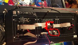
No joy. I'm beginning to think there is a flaky connection on a trace or another component. If I press down on the board away from the main power connnector, sometimes just the slightest of touches, I can get the power back but it wont stay on for that long. This is making me think it isn't the power connector. Problem is all the components are surface mounted, traces hidden.

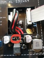
EDIT - Pic added -so if I press even gently on the components ringed or the board under the red squiggle I get power back.

BW.JPG


Kind of losing the will to live with it tbh :rolleyes: Anybody want to buy a borked Baywatch ...I'll throw in 10 other pins as well :rofl:
 
Last edited:
I’m positive the 18v connector is all good both connector and board side.
Even with the screen dead and power light off I get good readings at the reverse of the board.

I’m sure now the problem lies elsewhere …. but where ???? All surface mount stuff so hard to work with. Like I say pressing or flexing the board it will spring to life .
 
Last edited:
inspect all the smd solder joints. it’s possibly a leg on something that’s not properly soldered or has detached from its pad. really need a close up jewellers loupe or similar to look real close.
 
inspect all the smd solder joints. it’s possibly a leg on something that’s not properly soldered or has detached from its pad. really need a close up jewellers loupe or similar to look real close.

@AlanJ
Good shout - dug out a decent magnifier , and had a good look at components in the area. Well waddya know …. R32 looked a bit iffy at one end compared to others .

66608E57-D487-45BE-AE77-CCF9A3D2029E.jpeg

Confirmed with the gentlest of pressure on it - display powered on . Tiny dab with the hot iron and we are back in business 👍


I prob should have done that at the outset - tiny press on each component to identify the dodgy one , but sometimes you go off on the wrong track with trouble shooting. I was so convinced at first that it was the connector .

So now have power back I can try and figure out why it’s not displaying anything beyond the logo screen.
 
R32 looked a bit iffy at one end compared to others
That resistor was sometimes changed after the boards were produced. The voltage from the DC-DC converter needed adjusting to drive the LED panels properly.

From memory the voltage needed to be lowered.. although it says 3.9k on the board, my guess is that it's really 4.7k to drop the panel voltage to 4.17V. On the original 3.9k resistor the voltage was 4.77V and the LED panels wouldn't sync properly.

Sometimes R31 is replaced - to acheived the same result. For the techies amongst you... the XL4015E uses the following to determine an output voltage:
Vout = 1.25 *(1+R31/R32)... so
11k/3.9k = 4.77V (stock build)
10k/3.9k = 4.45V
11k/4,7k = 4.17V
10k/4,7k = 3.9V

So that's why that one resistor was soldered a bit sub par compared to the others...

Thanks Mike. Interesting - above my pay grade that info but good to know 😁

Ok the display is back in action . I didn’t do anything else and it’s running again .

AE5EC796-1FAA-451C-83F7-F1922377011C.jpeg

I suspect as others said that lowish 5v is causing the occasional display issue as it’s borderline , even though I have the recommended 5v display wire mod it’s low coming off my power board (4.8v) - and that needs addressing.
The R32 issue was a coincidence and made the problem seem more catastrophic 😁

Shout out to @Spandangler and @David_Vi for the cross checking on your machine.
 
No problem.

When I tested the voltage, I tried removing the connector and reseating and the display freezes, then resumes which is the same issue that sometimes happens during gameplay. Which does indicate that connector or the voltage dropping.
 
Back
Top Bottom