OP
OP
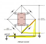
Yes mate that's right. The FET bridge is how the GI OCD and Afterglow create power from the 6.3VAC (J115), and it appears as though when the ground generated from this process is combined with the pinballs GND, it creates in imbalance that results in the chase board showing reversed LEDs dimmer than they should be.
Sick of me yet?!
So I can't alter these boards, or that FET bridge, or how the GND from that bridge is combined with pinball GND. The only option I'm thinking of now is to bypass that bridge, and power those boards some other way. The don't need the AC lines after all.
Sick of me yet?!
So I can't alter these boards, or that FET bridge, or how the GND from that bridge is combined with pinball GND. The only option I'm thinking of now is to bypass that bridge, and power those boards some other way. The don't need the AC lines after all.
")