What's new
Pinball info

Register a free account today to become a member! Once signed in, you'll be able to participate on this site by adding your own topics and posts, as well as connect with other members through your own private inbox!

Memory problem on a 1987 Williams Fire

Pie Man

Site Supporter
Joined
Apr 16, 2016
Messages
278
Location
Blackburn
I have a problem with my Williams Fire
I have changed the batteries but the machine isn’t keeping memory when turned off ie for free play, the diagnostics LED on the board is flashing does this tell me anything? the game seems to play absaloutly fine.
Any help would be appreciated.
 
Any sign of battery corrosion ?
You can trace the voltage from the batteries with the a multimeter.
 
Hello
No it’s all very clean around that area. I have also put a few different sets of batteries in.
 
Isn't there 2 diodes in the battery circuit. If one of these has gone open then when you switch off there's no battery backup. Or check you have 4.5v+ at the diodes incase there's a problem with the battery holder
 
Last edited:
Ok getting a bit technical now, please can you explain how to test with my multimeter, sorry for being dim, i would like to learn and understand though
When I turn the machine on it shows Adjustment Failier
 
ok iv had a look on YouTube how to do this and it seems pretty streight falward. Could you advise which diode/diodes are the ones I need to be testing.
 
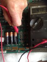
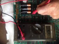
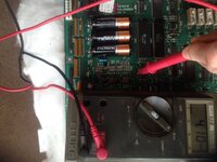
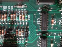
IMG_0612.JPG IMG_0614.JPG IMG_0615.JPG IMG_0616.JPG Ok. With the machine OFF put your dmm in dc test. Looking at the board in situ on the left hand side of the batteries locate D1. Put your black lead on the - (minus) side of B3 (battery3) put yr red lead on the top (non banded side) of D1 and see what it reads. I just grabbed a spare board to take pics of for you but my boarb is upside down yo yours. Mine reads 4.48v. Now put yr red lead the other side of D1 (the banded side) and read what it says. (mine read 4.10v). Now locate D2 which is found to the left of the batteries and to the left of r69. With black lead again on B3 put yr red lead on the banded side of D2.my reading is 4.10 but i just grabbed 3 batteries which could be a bit down. Yr readings i'd expect to be higher. On the non banded side of D2 you shouldn't have a reading. See my pics.
 
Wow I can't believe how you've taken the time in doing all that for me, thankyou very much I realy do appreciate this. I'll report back thankyou.
 
Ok I've done the tests on D1 the arrow side I get 337 the none arrow side I get 0 on D2 on the arrow side I get 337the none arrow side I get 370.
 
This don't make sense so put the black lead on B3 and the red lead on B1 which is the pos side of battery 1. If you're using new batteries you should get a reading of 4.6 to 4.75v or in that area. If not you have a problem with the battery holder and you may have to remove the batteries then desolder the battery holder. It's pointing to a broken trace under the holder to me.
 
Ok it’s showing a 0 reading. I have also taken each battery out and tested individualy and it shows 1.61 on each one.
Does this mean there is a fault with the holder do you think
 
Yes. The fault is either on the battery holder and/or a track under the batt holder. Carefully unsolder the battery holder from the board after you've removed if from the backbox. I'd mark every plug before you start so you know where they go. Yes it's a pain but it's the only way as the solder is on the back of the board
 
Ok thanks I’ll need a bit of time to do this, what should I be replacing it with? the same
one of these fittings that do the same job without the batteries. I’d probably be better getting this before I start.
 
My guess is that under the battery holder one of the tracks has broken. You need to carefully desolder the bat holder and examine the tracks that run from the pos to neg where the holder is soldered. You won't see anything till the batt holder is removed. The tracks are quite wide, not thin. Look where the track connects to the through hole on each of the holder pins. My guess would be the fault is around B1 area on the board.
 
Hello, Simon,

The three AA cells in series make up the battery, so you could check the holder itself by measuring from the -ve of B 3, or the machines' earth (using the black lead) to the +ve of B1 (Red lead). If the holder and the traces under it are good, the full voltage of the battery should show, around 4.5V. AIR there's a screened marking on the board, saying something like 'B +' (not just 'B'), with an arrow pointing at a solder point. This is the backed-up supply for the Cmos Ram - with the mains off this should show the battery voltage, less a little lost across one of the diodes (again measured with the black lead earthed)
 
Make sure you haven’t put the batteries in upside down. Naturally we want to put the positives towards the tops, but these should have the positives pointing down.
 
Ok thanks every one for your help on this, after carrying out and going through the various test. I was just about to take the connections off from the
board when i noticed some slight corrosion to the negative of B1, when cleaned i tested the voltage and straight away it read 4.50v, turned the machine
on set to free play then off and on again and its working fine. Big thanks to paddy the geek and J for giving me the advise on where and how to test,
Iv learned quite a lot. Thanks very much Simon
 
Back
Top Bottom