What's new

Johnny Mnemonic Service Bulletin

Carl Spiby

Registered
Joined
Feb 24, 2013
Messages
2,707
Location
Kendal, Cumbria
Just a little advise, my JM keeps blowing the fuse that controls the hand magnet, ball popper and autoplunger. It looks like my JM hasn't had the service bulletin fix done to it looking at this picture.
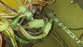
IMG_20150416_222740.jpg

I've read the service bulletin and I just want to make sure I've got this right. Is the idea to cut the red/brown wires on the left of that plug, leaving one wire longer so I can solder a jumper on to and route it into the back box then twist together and dress the remaining ends?

Where would I find 8ft of 18ga jumper wire?
 

Attachments

  • Williams_1995_Johnny_Mnemonic_Service_Bulletin_87.pdf
    32.9 KB · Views: 19
8ft ? Don't think you will need that much.
I have a few old looms you should be able to get off what you need.
 
Yes, you are correct Carl. Although I would solder rather than twist ends together. The service bulleting doesn't actually say what to do with those ends per say but I think it would be the correct thing to do.
 
Soldering wires together is bad practice. Solder is for electrical connections and is not designed for any mechanical fix.

Crimp at minimum but I'd heat shrink too.
 
Soldering wires together is bad practice. Solder is for electrical connections and is not designed for any mechanical fix.

Crimp at minimum but I'd heat shrink too.

Are you saying that a Crimp connection is better than a soldered one???!!!!!
 
When connecting wires together, 100%.

EE lesson 1 - solder is for electrical connections not mechanical.
Also, soldering together wires means you have two weak 'bend points', when a good crimp means you don't.
 
You are contradicting yourself.
We are connecting two wires together carrying electrical current. Not piano wire.

As you say - Solder is for electrical connections. This is one.

If you want to ensure a good connection between two wires carrying electrical current, Soldering is the way to go. Add some heatshrink if you wish to insulate the connection and make things a little more robust...
 
Load of shyte.

A wire is BOTH a electrical AND mechanical device. All electronics/electrical systems are. Hence why any connection needs to be BOTH.

A solder joint is an electrical connection with the potential for huge fatigue issues. While a crimp one is BOTH. That's why almost the entire aerospace and car industries use crimps. That's why all safe electrical equipment uses crimps. That's why the grounding of pinball machines uses crimps. Etc etc.

If a job's worth doing, it's worth doing properly. A soldered together wire is a hack but if that's all you have, it's better than a chocolate block!
 
I have twisted and soldered plenty of wires on pins, never a problem. It's a pinball machine, not a billion dollar military spec spacecraft :)

It's not about there being a problem, it's about doing things correctly. T

For the same of a 10 quid tool and some crimps, you might as well.
 
I hate to agree with the argumentative fool, but on this issue I agree with abaxas. Think it has been discussed briefly here before too, but my old electrical engineering training taught that a good mechanical solderless connections are far better than soldered.

Solder is less electrically conductive than a metal to metal bond. Solder also has fatigue issues over age and temperature.

Like has been said. For these kind of tiny jobs the difference is not mission critical, but... if you want to do it proper, do it proper.
 
this is a funny read. educational though.

so .... to join two single wires together, if a crimp is the best join, what does that involve? a crimped-on trifurcon pin on one end, and on the other, does a single-female receptor have to be crimped on there as well?
 
seriously, i'm intrigued. what is being suggested as the best way to join two wires for electrical reasons as well as mechanical ones?
 
Red Channel - 0.5 - 1.00mm
Blue Channel - 1.5 - 2.5mm
Yellow Channel - 4.0 - 6.0mm

so for our purposes, which channels do you use with that one, abaxas?
 
yeah i know, but i mean for standard pinball connectors it's 0.156 vs 0.1 so which hole in abaxas' crimper?

that's a different and cheaper one than the one discussed recently in another thread and backed by @ronsplooter and @GrizZ - any opinions fellas on this tool?


pffffttt etc
 
I think the one abaxas posted about is similar (or possibly identical to) the ones you use for automotive electrics. It's basically a ferule which you simply put a cable into each side and the crimp tool squishes the metal around it to hold it snugly in place.

Only thing you have to be careful about is making sure that the ferule you use is rated for the voltages it's going to carry.

So it's a semi-permanent join whereas the crimp tool most people think of on here is the one for putting pins onto the end of a cable so it can then be used in a connector and joined/broken as required.
 
Back
Top Bottom