What's new
Pinball info

Register a free account today to become a member! Once signed in, you'll be able to participate on this site by adding your own topics and posts, as well as connect with other members through your own private inbox!

Is this ghosting? Or a wiring fault?

Durzel

Registered
Joined
Oct 1, 2017
Messages
2,041
Location
Bath, UK
I spent the entire day today fitting a full LED kit to my friend's Funhouse. Everything went relatively smoothly, but when I played a game after I'd finished there was a lot of random light issues. It wasn't sold as a non-ghosting kit so I have no reason to assume it was.

I'm inclined to think this is ghosting, but I don't have much experience with spotting it. In test mode several of the inserts light two at once, but not in a dim residual current kind of way - they properly light up. There doesn't seem to be any sense to it either, even a jet bumper light comes on with one of the inserts in test mode.

The magic mirror lights several bulbs at once at the start of a game, instead of just one flashing one.

Here is a video demonstrating it:

The machine is running ROM version L-2, which I understand is an old one. It's probably the one it came with. Is it fair to assume that a Funhouse without a ghosting patch is going to ghost with LEDs guaranteed?
 
Last edited:
Ghosting is normally dim.

Looks like a shorted transistor on the driver board to me. Easily done by accident when changing bulbs while switched on!

Check Q92 on the board with a meter , if it’s all the magic mirror lamps, upper right jet bumper and P of STEP staying on, all in the same column on the lamp matrix.
 
Thanks.

It's a combination of inserts coming on at the same time, not just the magic mirror. I thought maybe optimistically it was ghosting but the bulbs are actually coming on, it doesn't seem like residual voltage, and some inserts seem to be unaffected completely.

For the most part I installed all the bulbs with the machine off, though there were some that were reseated while it was running

Will go run a bulb test and report back. Thanks very much. While I'm at it - how do I test Q92? Do I do it with the machine off? What settings do I use on the DMM? And where do I put the probes? (sorry I'm very much an electronics noob)
 
Yes turn machine off. Put meter on continuity test, the mode where if you touch the probes together, meter will bleep indicating a short. Put one probe on the metal casing of transistor with hole in (which is the same as the middle leg), the other probe on each outside leg, if meter bleeps the transistor is shorted and needs replacing.
 
I don't know if it's relevant but when I unplugged J116 to plug in a LED strip the grey wire just fell out of the connector. I don't have a tool to put it back in, so I just pushed it back in with a mini screwdriver. It would come back out again if the connector moved at all, so it needs work to fix properly, but everything still appears to work.

I also dropped a wood screw holding one of the GI bulb holders somewhere in the machine. I wasn't able to find it, but I checked everywhere I could see, even removed some boards to see if it had become wedged behind, but no luck. Don't know what I can really do to find it?

Annoyed with this outcome because I was very careful and spent about 8 hours doing these LEDs yesterday.
 
I bought a telescopic tool, and my nut drivers and screwdrivers are magnetised, but alas this screw must've caught something as I was removing it and it plinked down like one of those 1p/2p machines at the fair before vanishing into another dimension. :(

Did also check the speaker but no joy.

Will report back with the lamp findings as soon as I can.
 
I bought a telescopic tool, and my nut drivers and screwdrivers are magnetised, but alas this screw must've caught something as I was removing it and it plinked down like one of those 1p/2p machines at the fair before vanishing into another dimension. :(
.

Did you hear it land? Screws often decide to play hide and seek in the wiring loom on the way down I've found.
 
Ok, done some testing..

Definitely not ghosting...

(Lamp 81) Million Plus - also lights (Lamp 71) Mirror Extra Ball
(Lamp 82) Special Lamps - also lights (Lamp 72) Upper Right Jet Bumper (white)
(Lamp 83) Trapdoor Frenzy - also lights (Lamp 73) S-T-E-P "P"
(Lamp 84) Ramp "Steps" - also lights (Lamp 74) Mirror Light Million
(Lamp 85) Mirror Value - also lights (Lamp 75) Mirror Jet Bumpers At Max
(Lamp 86) S-T-E-P "E" - also lights (Lamp 76) Mirror Light Super Dogs
(Lamp 87) Million - also lights (Lamp 77) Mirror Open Gate
(Lamp 88) Start Button - also lights (Lamp 78) Mirror Quick Multiball

Every other lamp works as expected, and the GI is fine too. Haven't yet checked Q92, as once I realised there was a pattern it seemed to be more like a lamp matrix short of some kind.

Interestingly, lamp tests on 71-78 don't illuminate 81-88, they just light up as normal, it is only 81-88 that has problems.

Not knowing hardly anything about electronics, how would I ascertain what is going on here?

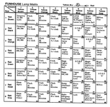
Looking at the lamp matrix table - it is clear that columns 7 and 8 shorted somehow.

Screenshot-2018-4-22 Funhouse_OPS pdf.png
 
Last edited:
Made some progress.. sortof

Most of the inserts that trigger another to light are actually on a PCB, they're those twist off #555 ones, so no diodes there.

And with the exception of two the ones that get erroneously switched on are on the mirror - which is another PCB.

On a whim I removed the connectors from the Start button - one of the remaining inserts in circuit with problems (I was going to replace it with an LED). With the connectors unplugged, there is no more double light problem - all the bulbs test properly.

I reattached the connectors and put a bulb back in, problem came back.

Took bulb out, problem went away.

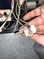
Is this the correct wiring for the start button? It starts a game properly, and lights a bulb if inserted.

224CDDE4-0320-46B4-BC91-1BEF4450CE6C.jpeg
 
Is the start button always lit?
Should it be always lit?
If you take the game off free play is it always lit?

Is the start button bulb led or incandescent?
 
No, start button illuminates when you expect it to.

Haven't tried taking it off free play.

It was an incandescent, but wasn't illuminating in test mode (single lamp) and was only coming on dimly when in attract mode.

Changed it to an LED, which lights up in test mode.

When either incandescent or LED bulb fitted to start button, game has lamp matrix issues. With no bulb in, it doesn't.
 
Last edited:
I am not familiar with the game or this generation of machine so I am only throwing things in to hopefully trigger a moment of brilliance from someone more experienced then myself.

The next logical thing I can think of is to plug the start button all back in and then remove one of the connectors from either of the effected lamp boards and see if you get the same result as the start button. Then repeat with the other board.

If nothing positive happens I would then trace the cables from the start button back to the head to make sure they have not been pinched anywhere.

Also try taking the bulb out of 'Magic Mirror, lights quick multi-ball" (56) 78 and see if anything happens.

Good luck.
 
Thanks.

My current thinking is that looking at the start button assembly pictured above the spade (?) on the bottom, which seems like it would be the ground, is charred pretty badly - for reasons unknown. It's possible it's not making good contact.

I also don't know if the start button is wired correctly, although the switch works (starts a game) and an installed bulb illuminates.

Though why this problem has only just manifested now that I've put LEDs in - who knows.

I did a very thorough inspection of the underside of the playfield and I didn't see any diodes that were touching anything else. Most of the inserts on Funhouse are those twist #555 types anyway.

The start button apparently has a diode in the coin door that I also haven't checked yet.

For the moment the game is working as normal with no bulb in the start button, so at least I have a baseline to work with and (I guess?) this means it isn't likely to be a knackered transistor on the driver board?
 
Doesn’t look to be any problem with that switch lamp, the charred spade is just the switch itself, which is not related to the lamp circuit. The switch and lamp housing can be separated, both work independently.

Shorted transistor on board would cause all lamps to stay on in a column or row so not that in this case.

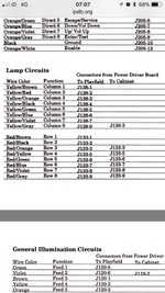
Question is, why are both columns 7 and 8 lighting? I’d be checking the related wires, yellow/violet and yellow/grey for a short.

It would be unlucky but maybe that lost screw is wedged between two lamp connectors?

Trace the yellow/gray wire back from the start button, see if anything’s amiss.

58826B17-2D09-4816-A06B-7778672A0986.png
 
Last edited:
Thanks, that's very helpful. I'm not in front of the machine at the moment (work) so will have to trace the wires later. It's possible that somewhere in the circuit that legendary missing wood screw is present, though I have looked very closely at all the wiring and the looms, and haven't been able to find it thus far.

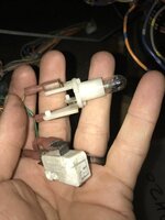
Regards the start button - so the red & yellow wiring is for the lamp, and the green is for the switch.. what is the purpose of the remaining wire? Is the extra prong with no wire attached significant?

Also, looking elsewhere on the web - I found this photo - which appears to show the red & yellow wires transposed to how mine is wired. I can't quite tell from your photo if yours is the same. Would that be significant? I assume the bulb wouldn't light at all if they were wrong, which mine does....

Also - is it significant that in lamp test it was only 81-88 that were lighting 71-78, not the other way around?
 
Last edited:
No not significant, only the same as you can insert a bulb in either way round. Two wires for the switch, two for the lamp.

As you say, the lamp comes on so no problem there. But the puzzling thing is why column 7 lamps lights at the same time as column 8. They are on different circuits so should be no connection. Makes me think somehow the yellow/gray and yellow/violet wires have become connected when they shouldn't be? Anyone else agree with this?
 
I don't know much about electronics, but I would've assumed a short would mean columns light eachother.. I don't really understand how it can be one way (Column 8 lighting 7, but 7 doesn't light 8). Obviously something has to be wrong for it to be happening at all though.
 
Thanks. I did see that while I was searching for help, and it does describe the problem, although it talks about columns lighting eachother, rather than being one way. Also the language ("logic probe", etc) unfortunately went completely over my head :(
 
Agreed the symptoms don't sound the same. You could rule out any board problem using the jumper and bulb method described in the bottom of that article.
 
Hi,

A couple of things I can add;
  • All individual feature or 'insert' lamps in the matrix have an isolating diode - a lamp or lamps on a pcb will have its/their diode(s) on there with them
  • The lamp in that 'Starpoint' button holder for the Start button has the diode on the Door Interface pcb inside the cabinet l/h wall, so the terminals used on the lamp holder itself don't matter
  • The unused connecting tab on the button microswitch is simply to allow it to be used as a Normally Closed switch if required by some other application.
Since this problem is created by having a lamp in the button, I'd check the cabinet wiring, maybe by going into lamp test before disconnecting the 'Cpu' side of the Interface pcb. Specifically the connector bringing in the Column 8 lamp wiring.
 
Apologies, but can you expand on what you mean by "disconnecting the 'Cpu' side of the Interface pcb". Is this the PCBs on or around the coin door or to the left (facing the machine) near the start button? i.e. nothing to do with anything in the backbox?
 
Sorry, I should have clarified.

Yes, the Interface pcb in a u.k game with an electronic acceptor has four five connecting headers, with two on each long side. I refer to the two* towards the front of the machine as the 'door' side, and the two nearer the back as the 'machine' or 'Cpu' side. One of these will have the Yellow-grey wire of lamp Column 8^, and Red-grey of Lamp Row 8.

Having now looked at the schematic, the cabinet fittings (tilt, 'door open' switch, start button) use the top connector, J6. The specific diode for the Start button lamp is D 1

Reading back, I see that the Start button didn't work properly with a filament bulb fitted. There must've been something amiss there to begin with. According to the connector charts, cabinet matrix-lamp wiring, i.e. the Start button, originates from the Driver pcb, J 136 Pin 3 for Col. 8 and J 135 Pin 9 for Row 8


* there may be only one 'door' connector, if the particular machine has a door with mechanical acceptors
^ not according to the schematic
 
Last edited:
Ok thanks, I think I understand that.. will have a look later tonight when I can get in front of it.
 
Well, I haven't been able to get anywhere in resolving this.

The yellow-grey and red-grey wires appear to have continuity into the backbox. As far as I can see they travel from the start button along the left hand side of the machine then into one of the cable tidy tubes then into the backbox. From there they appear to terminate on J136. I don't really understand where J135 fits in.

Disconnecting J136 makes the start button stop illuminating, and the double light problem also vanishes. Removing the yellow-grey spade connector from the start button lamp does the same.

I've reached the end of my technical ability really. I don't really understand how to progress this any further, but thanks for the help.
 
Back
Top Bottom