What's new
Pinball info

Register a free account today to become a member! Once signed in, you'll be able to participate on this site by adding your own topics and posts, as well as connect with other members through your own private inbox!

Gottlieb sys1 psu repair?

Yes result! I snipped a leg of each diode but they fell apart! fuse now stays! Could I use 1N4007's instead for those? I will need to wait until the 7912 arrives (posted out today) as the old one is looking past it snipped soldered then snipped again lol.

Sorry for running you round in circles I thought I had metered all the diodes, I missed those 2! Is there anything further I should check whilst waiting on the 7912?

And thanks again for your help with this, I would be tering my hair out lol

Thanks Ronnie
 
OK, you can now check the +5V (and regulate it with the trimmer) as well as the +4V, +8V, +42V and +60V. Use the right ground. You can use 1N4007 as a replacement, obviously put them in the right way round. Add the additional fuses.
 
Last edited:
All voltages are good, it's freezing in the garage! Just the -12v and hopefully that's it, I also added the ground mod wire to the psu, once that's up and running will add the 2 fuses and look at the connectors around cpu and driver board, also the EMI filter has been bypassed!

Thanks again Ronnie
 
Still not got the 7912's! not had mail for over a week! Just as well it's been too cold to do anything
 
Right, at last it was mild enough in the garage to work on this! So I fitted the new regulator and 2 diodes re fitted the board and checked the voltages, all good now and machine is back up and running! Big thanks to @drhex for his help with this.

The only thing not working is the ball kickout, grounding the tab on the driver board does fire the coil and the transistor seems to test good, so either bad wire from cpu to driver board or something else on the driver board, hopefully not a spider chip issue!

Thanks Ronnie
 
Happy to help, let me kow if you need support with the kicker.

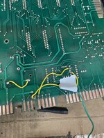
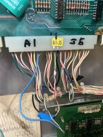
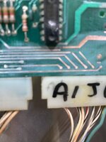
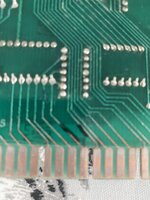
Brilliant thanks, I think I have found the problem? Z6 (7417) on the cpu pins 1 and 2 trigger the outhole kicker, followed the repair guide, tapping +5v to these pins should trigger the coil, but only pin 2 triggers it, I'm hoping the 7416 is bad? Have ordered a couple. Some repair work to do on the cpu board! one of the copper pads is missing to the edge connector that goes to the driver board, a bodge has been made soldered directly to the board, a couple of corroded tracks have been jumpered on the solder side, I will repair all that also, I need to get some of these connector pins to repair the hacked wires!

Ronnie
 
Your analysis makes sense, should be the problem. Socket it while you are at it.
 
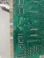
Some pics of the mpu showing the hacks
 

Attachments

  • EC3641A6-5E39-4B3E-A2A6-934132755BE3.jpeg
    EC3641A6-5E39-4B3E-A2A6-934132755BE3.jpeg
    164 KB · Views: 9
  • 60099009-C686-4214-AC40-C4A1960751D3.jpeg
    60099009-C686-4214-AC40-C4A1960751D3.jpeg
    138 KB · Views: 9
  • F0C057B7-B3DA-4F0B-B89D-8707FDB07167.jpeg
    F0C057B7-B3DA-4F0B-B89D-8707FDB07167.jpeg
    83.7 KB · Views: 8
Not sure what happened here but best would be to replace the connector. The board hacks can of course be done much nicer.
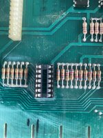
I have ordered some new crimps for the connector and hope to replace the cut wires, the damaged pad I have used some copper tape and hope it holds up as it will not be as solid as the etched on copper pads that are on the board, already fitted a socket for the 7417 and used thin wire to replace the damaged tracks component side and sealed with solder resist, will take some pics.
 
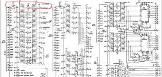
One thing confusing me about the 7416 is that pin one has no connection on the pcb? Should that not be the pin the cpu sets high to then set pin two high?
 
Ok that’s strange! I have already fitted a socket but pin one is not connected to anything?
 

Attachments

  • 75D12C85-6F6E-456F-A3CF-3FBF0C7330CB.jpeg
    75D12C85-6F6E-456F-A3CF-3FBF0C7330CB.jpeg
    106.6 KB · Views: 8
  • 3683ACF0-2014-4ACA-9858-BB2DBB616579.jpeg
    3683ACF0-2014-4ACA-9858-BB2DBB616579.jpeg
    94 KB · Views: 8
Schematic here showing pins 1 and 2
 

Attachments

  • Screenshot (9).png
    Screenshot (9).png
    108.6 KB · Views: 3
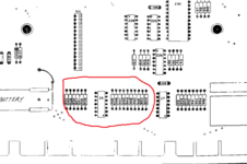
notch to the top of the picture? Looks like a trace to the top left contact?
 
notch to the top of the picture? Looks like a trace to the top left contact?

I thought at first notch at the top but it's bottom if that's correct pin 2 fires the outhole?
 

Attachments

  • Screenshot (10).png
    Screenshot (10).png
    23 KB · Views: 4
Could be the trace at the bottom left goes between the pins to the other side.

It must be, just waiting on the new chip now and the crimps for the edge connector, I will chance my copper tape repair and hope it's ok!, I might try and lift a pad from a scrap board and bond it to the board. all the hacks have been sorted will post a pic shortly
 
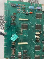
Corroded tracks repaired with kynar wire and over coated with solder resist, and pic showing pad and hacks gone
 

Attachments

  • 073D1760-7EFC-436A-8CAF-B51D87A7BCB8.jpeg
    073D1760-7EFC-436A-8CAF-B51D87A7BCB8.jpeg
    197.6 KB · Views: 7
  • 49DA1518-9368-478E-9F82-2A10C74ECACB.jpeg
    49DA1518-9368-478E-9F82-2A10C74ECACB.jpeg
    194.3 KB · Views: 7
Back
Top Bottom