OP
OP
")
I've ruddy well misplaced my manual! ARRRRGGGGHHHHH
Whilst doing this fiddling the 0A string of BB feature lights are back on again but I've now noticed that G Arrow and L (of GOLD) Arrow feature lights are out on the PF - most likely a duff SCR on A3 as these are close on the PF.

also try swapping over the GI FLASHER MODULES, both of which are mounted on the back of the light board


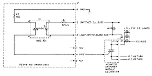
WIRING DIAGRAM BACK BOX in the manual
You warned me of such in your very first message to me!I need to stop trusting the crappy manual
Looking at the A3 schematic they list the flasher twice on J1-21 as though its on 0A and 0B like any other SCR controlling two feature lights. This page isn't clear in the online manual so difficult to read but it looks like it's leading to Q8.both flasher modules are controlled by the same lamp driver SCR as both are labelled as connected to A3J1-21
Today's mission is to find this and re-flow the flasher boards.There us a #44 lamp across pins 2 and 3 of the flasher module
Mmm... I'd want to know the part number or have the datasheet. These TRIAC optocouplers come in two flavours: Zero Crossing and Non Zero Crossing. If I recall correctly the MOC3011 is Non Zero Crossing. CPC don't have the MOC3011 (rated at 250V) but they do have the MOC3022 rated for 400V. I think it would be a suitable replacement: http://cpc.farnell.com/fairchild-semiconductor/moc3022-m/optocoupler-triac-driver/dp/SC12309No joy with the re-flow so I want to replace the MOC3011, is this at Maplins any good?
http://www.maplin.co.uk/p/high-voltage-opto-isolator-ay44x
Thank you for going to all that trouble - I just wanted to crack on with the job. I'm sure eBay is the route this one is same brand as FarnellI contacted Maplin


 What a nice man. Very nice man.