Pinball info
You are using an out of date browser. It may not display this or other websites correctly.
You should upgrade or use an alternative browser.
You should upgrade or use an alternative browser.
GI issues with my Addams
- Thread starter Annualman
- Start date
Have you got a multimeter? And a wiring diagram for Addams?
Turn it off and look for continuity along the chain. Start at the end that goes to a connector. Could be a loose wire to the connector. Or a break before the first bulb that is out
Turn it off and look for continuity along the chain. Start at the end that goes to a connector. Could be a loose wire to the connector. Or a break before the first bulb that is out
I have a manual - and yes, just acquired a multimeter - will search for breaks/loose wires. Thank you. - are they wired in series?Have you got a multimeter? And a wiring diagram for Addams?
Turn it off and look for continuity along the chain. Start at the end that goes to a connector. Could be a loose wire to the connector. Or a break before the first bulb that is out
Mike
First thing to do is check the fuses out of the game they may look ok but that’s not always the case
Next step take a good look at connectors j115 bottom left on the driver board and j121 j120 look for any burning or Charing pull them on and off a few times and check the wires where they are pushed into the connectors better still upload a pic or 2 of the connectors
Next step take a good look at connectors j115 bottom left on the driver board and j121 j120 look for any burning or Charing pull them on and off a few times and check the wires where they are pushed into the connectors better still upload a pic or 2 of the connectors
thank you,First thing to do is check the fuses out of the game they may look ok but that’s not always the case
Next step take a good look at connectors j115 bottom left on the driver board and j121 j120 look for any burning or Charing pull them on and off a few times and check the wires where they are pushed into the connectors better still upload a pic or 2 of the connectors
will get checking,
Mike
Im sure one of the GI lamp sets on mine went off - which I recall was the connector wiring.
As Chris B said really.
I've had the weight of the wiring at the Molex connector pull that connector downward slightly at the board. A slight lift upward of the connector so it's at 90 degrees and they all came on.
Knowing those poor factory connectors I'd be inclined to blame the connector.
I've had the weight of the wiring at the Molex connector pull that connector downward slightly at the board. A slight lift upward of the connector so it's at 90 degrees and they all came on.
Knowing those poor factory connectors I'd be inclined to blame the connector.
Hi @Annualman pinwiki section 6.25.2 General Illumination Problems has a good write up and some nice animated graphics that explain the GI circuit very well, would recommend getting familiar with that along with the helpful replies on here, good luck I'm sure you'll get to the bottom of it.
 pinwiki.com
Williams WPC - PinWiki
Many, many thanks to all for the helpful advice. I feel confident to have a look and see what's up if I can - tomorrow may be less hectic than today so hopefully will get a chance.Hi @Annualman pinwiki section 6.25.2 General Illumination Problems has a good write up and some nice animated graphics that explain the GI circuit very well, would recommend getting familiar with that along with the helpful replies on here, good luck I'm sure you'll get to the bottom of it.
Williams WPC - PinWiki
Will report back either way!
Ok,
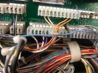
so connectors seem ok. pinwiki section 6.25.2 said check output at 120 - my problem circuit is brown - so checked fuse after removing it (that was tough)and then the outputs at pins 1 and 7 - nothing. I then did 6 and 11 (violet - that gave me 7 v. so I deduce that the power is not getting to the brown circuit on J121. now what? I assume that the wiring under playfiield may be ok as power from board the issue?
Pics attached of connectors
Attachments
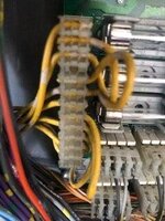
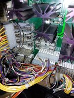
The connector in picture '2121' is the ac input wiring from the transformer. For the five illumination circuits, there are three input wires for each side of the ac circuit. Two of those wires serve two illumination circuits, by doubling back on themselves, while one illumination circuit only has its own lone wire. Going by the resistor colour code, I wonder if Brown circuit is the first fuse and the (topmost) lone wire(s). Is the ac input alright? measure using an ac voltage range between Yellow with white trace and Yellow. It looks as if the Yellow-white wires connect to the fuses, if so then measure between each fuse and Yellow to check on the connector itself
In fact, looking closely at that connector, what's happening with the yellow wire seeming to enter the lowest slot?
In fact, looking closely at that connector, what's happening with the yellow wire seeming to enter the lowest slot?
thank you, will look and measure inputs - no idea about lowest slot.. Bear in mind this machine was 'fully serviced' by HLD ( not for me, but previous owner) - so maybe some od fixes in past ??The connector in picture '2121' is the ac input wiring from the transformer. For the five illumination circuits, there are three input wires for each side of the ac circuit. Two of those wires serve two illumination circuits, by doubling back on themselves, while one illumination circuit only has its own lone wire. Going by the resistor colour code, I wonder if Brown circuit is the first fuse and the (topmost) lone wire(s). Is the ac input alright? measure using an ac voltage range between Yellow with white trace and Yellow. It looks as if the Yellow-white wires connect to the fuses, if so then measure between each fuse and Yellow to check on the connector itself
In fact, looking closely at that connector, what's happening with the yellow wire seeming to enter the lowest slot?
M
A look at the manual and schematic shows that the colours assigned to the illumination 'strings' do follow the resistor code, i.e. brown is No.1. But it's fuse 110, fed from pin 3 of the input connector. And its return is shown as pin 8. The lowest pin, No.1, is marked as a 'Ground Reference'
specifically for string 1, the pins are 3, leading to fuse 110, and 8, returning from Q 18. For comparison, the other pairs are 4 and 7 (fuse 109), 6 and 11 (108), 5 and 10 (107), 2 and 12 (106). This connector is one that Williams improved on, allegedly, in later games.
I was wrong about the Yellow-white wires being the fused side, btw. It's the yellow wires that connect to the fuses.
I was wrong about the Yellow-white wires being the fused side, btw. It's the yellow wires that connect to the fuses.
Last edited:
Ok - so this is what I know: AC power in seems ok, connectors 115 and 120 removed and replaced - no sign of damage.
Fuse removed and tested 0 ok.
Only issue I can find is no continuity from pin 3 of 115 to fuse 110.
Close inspection reveals odd mark to side of what is either pin3 or pin 4 of 115 - see pics.
Whilst I am keen to learn - I am unfamiliar with most of this - bear in mind the last time I used a volt-meter it was in the 1970's and it was a huge black thing.
I played my first pinball in 1974 and bought my first EM 40 years ago - as I had played it when new in 1976!!
All help appreciated......
Attachments
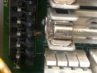
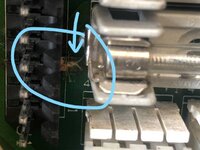
looks like that's the problem then the trace has blown out on the board between J3 and the fuse 110
That looks like a copper trace on the circuit board, with the green lacquer removed. If your meter has fine probes, does that have contact with the fuse? That black connecting header wouldn't have been fitted on an Addams original board, either. Maybe this is a later machines' board (nothing wrong or unusual about that), or the connector has been replaced.
Ok, so can a simple soul like me fix that?looks like that's the problem then the trace has blown out on the board between J3 and the fuse 110
You have found the issue, so next steps for repair are:
1. Take board out of machine (label connectors and take lots of pics of where connectors are first - whilst all connectors should be keyed to stop them being put in the often the keys can be missing on older machines)
2. Inspect J115 pins to se if OK (send photos to thread) - replace J115 connector if needed.
3. If pins OK, reflow all J115 connectors pins in case of cold solder joints. (and also F110 fuse clip if needed)
4. recheck continuity from pin 3 to F110 - if none then install jumper wire on back of board. between pin 3 and F110
5. Reinstall board.
Whilst doing this you should carefully inspect other GI lines at this connector and do preventative maintenance as nexcessary (e.g, don;t just reflow pin 3, do them all and also on J120 and J121.
Belt and braces is to also redo the wire connectors with trifurcon . new housings.
Last edited:
Even with keying pins in place, the Wpc driver board has a few connectors along the lower edge that are identical. J124, 128, and 132 are all keyed the same, as are J 123 and 131.
And when reinstalling board check and double check all connectors are installed correctly before turning on.
Takes a deep breath. Ok - will give it a go when feeling strong. Game plays well so not critical - not very confident I can do this - but nothing ventured......You have found the issue, so next steps for repair are:
1. Take board out of machine (label connectors and take lots of pics of where connectors are first - whilst all connectors should be keyed to stop them being put in the often the keys can be missing on older machines)
2. Inspect J115 pins to se if OK (send photos to thread) - replace J115 connector if needed.
3. If pins OK, reflow all J115 connectors pins in case of cold solder joints. (and also F110 fuse clip if needed)
4. recheck continuity from pin 3 to F110 - if none then install jumper wire on back of board. between pin 3 and F110
5. Reinstall board.
Whilst doing this you should carefully inspect other GI lines at this connector and do preventative maintenance as nexcessary (e.g, don;t just reflow pin 3, do them all and also on J120 and J121.
Belt and braces is to also redo the wire connectors with trifurcon . new housings.
thanks for the comprehensive advice.
Mike
But it might still be a quick and easy fix if it is just a cracked solder joint on pin 3 
Interesting, your 120 and 121 connectors are the opposite way round to mine.My TAF with belts and braces approach. Now board connector at J115, new housings with Trifurcon connectors at J115, J120 and J121.
