What's new
Pinball info

Register a free account today to become a member! Once signed in, you'll be able to participate on this site by adding your own topics and posts, as well as connect with other members through your own private inbox!

Sold Cool piece for a ‘Jaws’.

Slingshot99

Registered
Joined
Mar 1, 2020
Messages
230
Location
Northants
Alias
Someone else
Not mine but spotted it on eBay. How cool would this be hung from the head of your Jaws pin with sound and lights connected !
Ps don’t shoot the messenger🫣


Attachments

  • IMG_5081.jpeg
    IMG_5081.jpeg
    126.8 KB · Views: 54
it arrived, big n heavy, well built
IMG_8808.jpeg
IMG_8809.jpeg

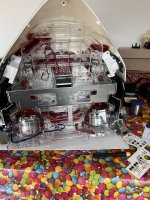
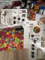
It has 2 speakers, 2 motors, a fan and lighting. There are 3 pcbs (maybe more) and a 30 pin connector on the rear.

Thus was from a fairly recent paschinko game “jaws 3 shark panic” made by heiwa of japan.

like most of these games. no schematics are available. so my only option is to try to reverse engineer it

First job was a tough one, getting to the first pcb with the external 30mins connector.

IMG_8818.jpeg
IMG_8820.jpeg
Got it out eventually.

The speakers are passive, ie both speaker wires are connected to the 30p connector, so the sound effects must have been generated by the main body part of the game.
IMG_8819.jpeg

So far i’ve figured out the motor part of the circuit, and looks like all the stepper commands come through a 595 shift register that has its clocks and input signals coming from the 30p connector again (via resistors and a 9541 octal schmitt buffer ic.

i’ve also figured out the power input. looks like 5v logic (but could be 3.3v) plus either 12v or 24v to drive the motors.

that’s taken me most of today to figure out, still a lot of the circuitry on this first board that i haven’t sussed out. the first board connects to the 2nd with an 18 pin connector and also connects to one motor, one speaker and an opto on the motor drive. board 2 connects to the second speaker, motor and opto.

This could take a while…….
 
I’d be hanging on the wall, Bluetooth to the speakers and an LED strip behind the teeth. That’d be good enough for a show piece.
 
I’d be hanging on the wall, Bluetooth to the speakers and an LED strip behind the teeth. That’d be good enough for a show piece.
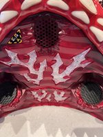
There seems to be leds in the eyes, the teeth and in the mouth roof, so would be really nice if i can get it to use all that as is.

I’m going to spend a few hours this aft on it again.
 
Getting obsessed with this f***ing thing ha ha
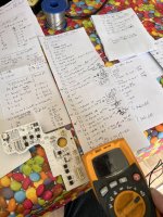
IMG_8824.jpeg

I think i have the motor control circuit sussed, there is also some sort of feedback info which i cannot figure out but that might become clear if i can get the motors to move in the first instance

i’ve worked out what most of the connector pins to the next board do. there is voltages 5 & 12, gnd, 2 speaker and 4 motor control. that leaves 3 un accounted for. 1 seems to be tied high to a resistor but cannot trace it anywhere else?

The other 2 are fed from the 30p input connector (via octal driver ic and resistors), so i think these 2 must control all the led lights.

I can’t easily get to the other 2 boards without a heck of a lot more dismantling, so i tried to identify the largest ic on each of these other 2 pcbs
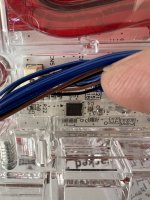
IMG_8826.jpeg

Eventually managed to figure it out as a toshiba tbd62d612g ic. That’s a pretty nifty yet complex to drive led driver chip. and it now makes sense as it only needs 2 control wires to drive it, which i have! Yey!

each chip sets a unique address by applying certain voltages to 3 control address pins, so in order to control it i need to get to those pins and find out their voltages. different addresses are set by using 0v, 1/3rd, 2/3rd, or full vcc voltage. so there can be dozens of possible addresses with 3 lines. I could try guess, but probably better to get to the boards and measure them. So a big dismantle job looms

i looked at the spec manual for the tbd driver ic. it’s complicated to drive, need to send an 8 bit address that matches the ic’s address, then an 8 bit sub address to determine which led circuit to control and then an 8 bit command. each led will be rgb and each r,g,b circuit is controlled via a different sub address. there are 24 outputs/sub addresses, 8 red, 8 green and 8 blue. or they can also be used to control up to 24 separate single colour led circuits instead. it’s going to be fun programming that lot!

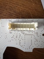
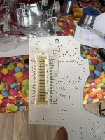
next i looked at the 30 pin connector:
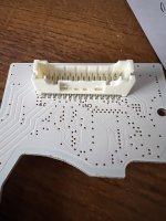
IMG_8827.jpeg
IMG_8828.jpeg

Looks like some sort of jst connector. i started there looking at jst ph, realised they are single row. jst phd series is double row, but nothing i found looked like it would fit. the pitch is 2mm.

Eventually found a series called JST PUDP and that looks like it may be the one, so ordered one and the crimp pins to fit it. £11!!!
I was tempted to de solder the existing and replace with something i have, but all my existing parts are 2.54mm pitch.

So, next step- dismantle more to get to the other pcbs………….
 
I don’t understand ANY of that but am seriously impressed! Does the motor referenced move the jaws?
 
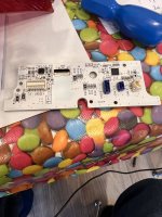
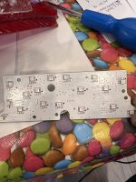
Got the second board out - control electronics on the side i could see, but a nice surprise on the rear - leds
2 different types
IMG_8829.jpeg
IMG_8830.jpeg

i’ve figured out the address of the led driver ic. it’s 3 address pins are set as gnd, 1/3rd and 1/3rd Vcc. so that gives an 8 bit address of 00001010 according to the chip documentation. the 1/3 Vcc is derived using 2 resistors 750 and 1500 as a simple voltage divider.

The Third pcb is really hard to get to, but i can now see the led driver chip and i think this one has its 3 address pins as 1/3,gnd, 1/3 which gives an address of 00100010.

not sure if the leds are 3.3v, 5v or 12v. will look closer at where they’re wired to, tomorrow.
 
Spent a couple hours putting it all back together this morning. Must have missed a few screws as i’ve got some left over! Might take it apart again and find out where they go!

Need to wait a week or so for the connector to turn up. Then the real fun starts!
 
Spent a couple hours putting it all back together this morning. Must have missed a few screws as i’ve got some left over! Might take it apart again and find out where they go!

Need to wait a week or so for the connector to turn up. Then the real fun starts!
Maybe the company have an Ikea connection? Anyway, you’re not a proper engineer if you don’t have stuff left over😉
 
Back
Top Bottom