What's new
Pinball info

Register a free account today to become a member! Once signed in, you'll be able to participate on this site by adding your own topics and posts, as well as connect with other members through your own private inbox!

In Progress Bally Vector

Nedreud

Registered
Joined
Feb 12, 2013
Messages
3,092
Location
Aldershot, UK
I won't be doing a full shop on Vector until I complete my project Paragon. The main point of buying Vector is to have another pinball machine that actually works! But to remind me of what I will inevitably have to repair along the way I'll keep things noted here. Hopefully bits and bobs will be of use to others.

So, since buying Vector on March 29th, 2014, I have:
  • Replaced the coin lock after key snapped
  • Re-soldered the braided wire to the tilt plumb bob
  • Re-secured the right slingshot mechanism as it was only being held on by 1 screw
  • Vacuumed and quickly wiped the playfield with Mill Wax
  • Discovered that "05" in the Player 1 displays at switch on is not a fault but an indication that I have custom game ROMS
  • Set all the game switch options and settings back to default
  • Reset the high score to date to zero
 
Last edited:
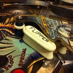
After a struggle to locate the right tool (http://www.pinballinfo.com/community/threads/bally-flipper-arm-grub-screw-size.11695) I managed to fit today the correct EM-style "FLIPPER"-embossed 2-inch mini-flipper on the upper-playfield:

image.jpg

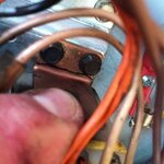
Sweet! I also replaced the sheared bolt on the coil stop bracket and fixed the missing plastic spacer in the EOS switch that meant the high current coil circuit was ALWAYS ON when holding up the main left flipper! Thought I might as well tighten all the nuts on the flippers as several were loose and I'd noticed the coil seemed rather loose on the main right flipper. That's when I spotted this:

image.jpg

The coil end stop bracket has sheared clean in half across the bend!
 
After a question elsewhere on pinballinfo about the size of screws used to secure ramps to the playfield, I removed one to measure it (3/4-inch long, head 7/64-inch diameter, Philips #1) and decided I might as well check them all. Not one of the 16 screws didn't need tightening to some degree or other! The centre left ramp is now noticeably more flush withe the playfield.
 
Fixed the cracked coil end stop bracket by replacing it with a rusty one I pulled off my old Paragon playfield. A temporary patch till I put together a parts order.

Have to say Vector is a f*** of a lot harder to play with that mini-flipper on the upper playfield, but after spending 20-30 minutes with the glass off dropping balls down the in/out-lanes by hand I have finally worked out how to nudge into the saucers with fair reliability and mostly without triggering the TILT.
 
Vector is on the back burner at the moment as I am concentrating 100% of my efforts on PARAGON. Also, it's buried under a pile of Celotex to stop me from playing pinball all the time instead of fixing PARAGON!

Next job is to fit a couple of brand new coil end stops to the two main flippers and I'm going to swap them over to see if the right really is weaker than the left or if it's all just in my head. The end stops have come from Pinball Mania but they're round at a mates.
 
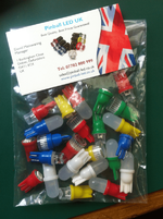
Ooh... look what just arrived in the post, a selection of insert LEDs in Concave, Superbright and Premium 2 types, and some Frosted GI. One of each in red, green, blue, yellow and orange, plus warm and cool white for GI.

Toying with the idea of converting Vector to LED as I think it might suit the naff future/retro theme! ;)

Pinball LED UK.png
 
Never seen a vector with LEDs before. Give it a go! :thumbs:
Indeed I will! Or have! Admittedly I've just stuffed them in without any modifications, e.g., resistors, etc., so the fact that anything works at all on a machine this old is a miracle. I will in due course do proper tests... this was just half an hour during my lunch break.

Respect to Dave Mainwaring aka @alchy at http://www.pinball-led.co.uk/ for getting my order to me in just 1 day!

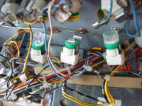
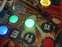
All the bulbs on Vector are #555 wedges. From left to right fitted in the 2x, 3x and 5x inserts are Concave, Superbright and Premium 2 in green:

farm4.staticflickr.com_3843_14420702286_b04a5806ef_c.jpg
Vector: LED Testing by staticboy, on Flickr

From left to right fitted in the 1, 2 and 3 THOUSANDS inserts are Concave, Superbright and Premium 2 in blue:

farm3.staticflickr.com_2923_14257214320_3430269990_c.jpg
Vector: LED Testing by staticboy, on Flickr

From left to right fitted in the 5, 10 and 15 THOUSANDS inserts are Concave, Superbright and Premium 2 in yellow:

farm6.staticflickr.com_5574_14443829605_60b7c16f8e_c.jpg
Vector: LED Testing by staticboy, on Flickr

Hard to take photos of flashing lights! But somehow I got the Concave and Superbright in green (2x and 3x) and the Superbright blue in the 2 THOUSAND:

farm4.staticflickr.com_3869_14443829565_fd7be1e402_c.jpg
Vector: LED Testing by staticboy, on Flickr


Warm White Frosted this time in the left slingshot and inlane/outlane guide:

farm4.staticflickr.com_3894_14420699146_2d954f9377_c.jpg
Vector: LED Testing by staticboy, on Flickr

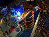
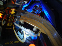
Under the front plastic is a Cool White Frosted and behind under the curved plastic a Blue Frosted. I'm not sure about either the warm or cool white, but do like the blue frosted GI under that insert. Vector has quite a lack of under-plastic GI so it would be great to add a load using LEDs without adding any extra strain on the power supply. In fact, as 1 incandescent is the same as at least a dozen LEDs the overall current draw will be lower even if I add 20-30 extra playfield GI lamps!

farm3.staticflickr.com_2914_14443829325_f310589de2_c.jpg
Vector: LED Testing by staticboy, on Flickr

And a couple of videos. Especially impressed with the Superbright in green on the 3x insert. Based on these very preliminary tests I prefer the Superbright over the Concave (not bright enough) and Premium 2.


I have a rather useful item which is hopefully in the post from the USA which will FINALLY mean i can carry out the comparison of LED's that a lot of people have been waiting for for a long time..... :D
 
I have a rather useful item which is hopefully in the post from the USA which will FINALLY mean i can carry out the comparison of LED's that a lot of people have been waiting for for a long time..... :D
Mmm... interesting! I look forward to that.

What Ihave discovered so far is it's all very subjective and down to personal preference and taste. For some I am comitting a heinous crime by even considering putting LEDs in a game as old as Vector. But I think it could work well with the theme if not overdone. But I probably won't even try it on Paragon. Also, I found different LEDs look better in locations they may not have originally been intended for: I thought the Frosted looked great in inserts but terrible in the playfield GI!
 
Nedreud, is there any ghosting? I.e. Dimly lit LED that shouldn't be on at all?
No ghosting. Certainly none that I can detect even using the video camera on macro. Ghosting is most commonly caused by a software "bug" in WPC systems coupled with shortcomings in the lamp driver matrix hardware. It's always been there but switching from incandescent to LED lighting just exacerbates the problem to the point it's noticeable too humans.

There is an excellent, if somewhat technically in-depth article, all about it here: http://emmytech.com/arcade/led_ghost_busting/

To the best of my knowledge and understanding of the Bally lamp driver circuit, ghosting shouldn't be an issue on systems of this era. The main problem is flicker caused by the SCRs not holding their latch after the control signal has been removed, but as detailed above this is easily cured with the simple resistor fix shown above.

I'm interested to have a look at LEDs such as "NoFlix" and "Ghost Busters" because they also contain a capacitor to minimise ripple in the supply but which can also give the LEDs a brief fade out rather than near instantaneous off mimicking incandescent behaviour. The LEDs from pinball-led.co.uk already contain the twin half-wave rectifiers and current limiting resistors which is how they can be plugged directly into AC GI with out modification. The surface mount component packed into the #555 base is impressive! I pulled one apart to see how it was done - will post a photo later.
 
You realise he's going to dissect my twin half-wave rectifier and current limiting resistors. Sob Sob :(
 
As promised! Stripdown destruction of LEDs! Actually, it's okay, there's a happy ending.

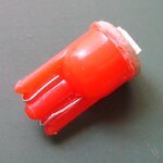
So, here's what's inside an orange Superbright #555 SMD Wedge. First up, using some small snips I nibbled the edge off around the top. Initially I tried prising the LED and its mounting base out of the casing but it seemed to be well stuck and/or glued. The contact wires are quite thin and each wraps around the bottom edge:

Pinball UK LED Stripdown 001.JPG

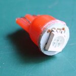
Here's the top showing the SMD (Surface Mount Device) LED. You can clearly see the 3 LEDs within the white circular lens area as small black dots:

Pinball UK LED Stripdown 002.JPG

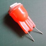
Next I unbent the legs:

Pinball UK LED Stripdown 003.JPG

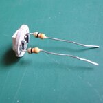
And slid the components out of the casing. So, you can see that the contacts on the outside of the case are actually the legs of the resistors inside:

Pinball UK LED Stripdown 005.JPG

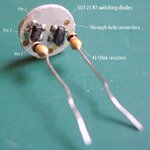
So, what have we got inside? Five components altogether: two 43Ω 1/8W Carbon Film resistors (yellow = 4, orange = 3, black = 1x multiplier, gold = 5% tolerance), two SOT-23 A7 Dual Switching Diodes and on the top a 5050 Package Triple LED. The two diode packages act as a full-wave bridge-rectifier. This is how these LED-based lamps can be plugged into an AC (Alternating Current) source such as the playfield GI. If they're connected to a DC voltage, such as feature lamps, inserts, etc., only one half of the rectifier is used.

Pinball UK LED Stripdown 004.JPG

As I don't know the exact specification of the LED I'll use some figures I found for a similar device: a Forward Voltage of 2.3V and a Maximum Continuous Current of 50mA. On a supply voltage of 5.9VAC in my Vector gives an ideal current limiting resistance value of 72Ω, so the two 43Ω resistors in series either side are about right (they're over-limiting a little and probably giving the LED about 43mA but this value has to cover a range of supply voltages, e.g., my Paragon kicks out 7.3VAC for the GI and many games use 6.3VAC).

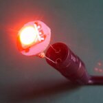
And just to show I have not killed the LED taking it apart, here it it running of 6VDC. Aftwards I poked the legs back through the case and bent them back around to reform the terminals.

Next I shall be experimenting with some smoothing capacitors... ;)

Pinball UK LED Stripdown 006.JPG
 
Last edited:
I'm a tinkerer, you see. I simply have to know how stuff works! Been pulling stuff apart for years. That's the easy bit. The real trick is getting it all back together again afterwards!
 
In this instance I needed to know how these little guys work because when I read forum posts (mostly US sites) on why LEDs "ghost" on this system or "flicker" on that system there's so much conjecture, inaccuracy and frankly total nonsense written. Now I know how they work I can make the appropriate mods for my systems and the. Look into making improvements. Anything I learn I'll share with community :)
 
It's all pretty straight forward stuff Peter. I was gonna do a similar thread myself but looks like you got this ;)

Anyone who doesn't know me, should be aware that I talk mostly ****. :wave:
 
I'm a tinkerer, you see. I simply have to know how stuff works! Been pulling stuff apart for years. That's the easy bit. The real trick is getting it all back together again afterwards!

I bet you were one of them kids that liked to play with dead things lol
 
Back
Top Bottom