What's new
Pinball info

Register a free account today to become a member! Once signed in, you'll be able to participate on this site by adding your own topics and posts, as well as connect with other members through your own private inbox!

In Progress Bally Playboy - Pinfest 2024 candidate?

AlanJ

Site Supporter
Joined
Dec 27, 2017
Messages
7,771
Location
Leeds, West Yorkshire
Alias
Alan
I Picked this up a few months ago, been sitting patiently in the garage awaiting attention.
IMG_8021.JPEG

The cab has been horribly repainted:
IMG_8018.JPG
IMG_8020.JPG

It should look like this:
backbox right.jpgcab side left.jpg

I bought it of a chap who has had it for over 30 years, about 15 years ago he bought a set of stencils in order to re-do the cab, but he never got around to it. He sold the stencils as part of the deal, but I'm not sure they will work, being so old.... we will find out later!

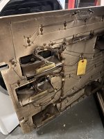
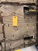
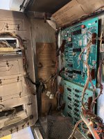
All boards are there:
IMG_8024.JPG

The rectifier board has been hacked with wires soldered to the header pins and some of the head cab wiring has been extended.....yuk:
IMG_8026.JPG

Before I do a full refurb on the cab, I thought it might be nice to get it up and running and take along to pinfest in August this year.

First job is to get a new rectifier board - and I already have one:
IMG_7995.JPG

Today I'll move the pin from the garage into the pin room, set it up on legs and get the head on, then remove the rectifier and transformer. The rectifier board on these early Bally SS games requires 12 wires to be soldered from the transformer to the rear of the rectifier board. Not the best design!

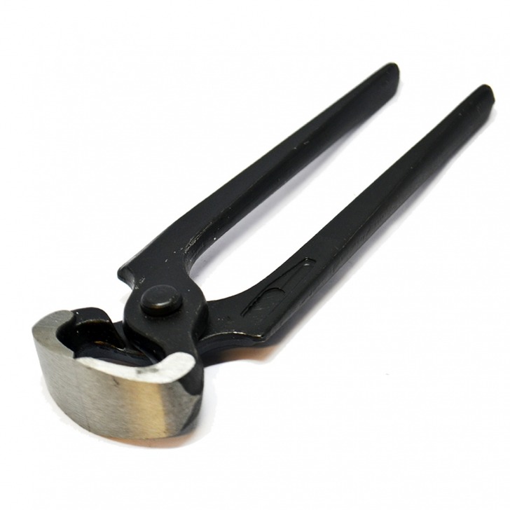
I'll then need to sort out the wires to the 3 rectifier headers and re-pin them.

1707471126028.png
 

Attachments

  • IMG_8027.JPG
    IMG_8027.JPG
    128.7 KB · Views: 19
looks like the playfield has survived quite well,has the original cab artwork been painted over,or is it in the weong cab?
 
Found a nos flipper coil in the bottom of the cab, but i can see i’m probably going to need it:
IMG_8031.jpeg
IMG_8047.jpeg

The wiring and connectors to the rectifier board is well dodgy
IMG_8033.jpeg
IMG_8036.jpeg
IMG_8038.jpeg
IMG_8037.jpeg

Took the transformer and rectifier out:
IMG_8035.jpeg
IMG_8034.jpeg
I hooked it up to 230v and tested it. very odd readings. the 7v ac is at 13v? the 44v dc is only at 22v. the 11.9v dc is at 5v and the 230v dc is at 158!!!

I checked the wiring on the back, and all correct, so are the ac transformer voltages, so it’s time to swap in the new rectifier board.

hmm:
IMG_8046.jpeg

The backbox and everything in it is covered in black dirt- like something set on fire 🔥 at some point in the past. The main cab is ok though. It’s absolutely filthy!

I replaced the rectifier board and repinned all 3 connectors. The funny coloured wire extensions are staying for the time being.

i checked all voltages correct before connecting up j1 and j3.

IMG_8045.jpeg
IMG_8049.jpeg
IMG_8050.jpeg

Powered up. GI and a locked on mpu led. at least there was no boom or magic smoke 🤣🤣
 

Attachments

  • IMG_8043.jpeg
    IMG_8043.jpeg
    165.2 KB · Views: 5
  • IMG_8044.jpeg
    IMG_8044.jpeg
    179.8 KB · Views: 5
Tried a few things to get the mpu to boot but it’s not booting. led locked on
IMG_8051.jpeg

So took the mpu and the sdb boards out to take a closer look

IMG_8057.jpeg
IMG_8055.jpeg
A bit of corrosion on the bottom of the mpu, but it looks pretty fair, no cracked headers and so i’ll clean up the headers and run some tests. I’ve got a bench test rig I built so I can test on the bench.

Sdb board looks fine too, but a few cracked headers need reflowing.
IMG_8058.jpeg
IMG_8059.jpeg

I tested all the coils and all are fine except the burnt out right flipper.

Plan for today is to get the mpu booting. If I can’t sort it easily, I’ll pop in. brand new mpu board I have spare.
 
Progress. I’ve now fixed the mpu board and it’s booting. I can start a game and got switches scoring and sounds. no flippers or solenoids.

I repinned j4 on sdb as not getting good readings
IMG_8061.jpeg
IMG_8060.jpeg

Still not getting the correct solenoid signals. At first i suspected U11 PIA on the mpu board, but it is generating sounds which use the same pia outputs as the solenoids. I tested u11 outputs and all ok. With j4 sdb disconnected the mpu is generating correct signals.

as soon as i plug in j4 sdb, the signals go funny.

I’ve come to the concluding u4 ca3081 is duff and so is us 74ls154, i suspect u1 and u3 might be too.

U4 is standalone, so i’ll replace that and see if i can get the flipper enable relay to work as that’s controlled by u4

IMG_8063.jpeg
IMG_8064.jpeg

not often i’ve got 5 soldering tools on the bench at once!
IMG_8065.jpeg
 
Replaced U4 on sdb and tried it.
IMG_8066.jpeg

I was pretty sure I’d got this sorted, but the flipper enable relay still doesn’t switch on when I start a game. Although I can trigger it by grounding U4 pin 3, which didn’t work before so U4 was deffo duff, but I still have another issue.

The flipper enable signal comes to u4 from the mpu u11 pia and specifically pin 16, which i’ve already tested and pin16 is going low when a game is started.Hmm. I’ve checked the wiring between mpu and sdb and that’s fine.

I next tested the output on the mpu j4 header pin 7 - this has no high or low output at all ????? Very strange.

U11 p16 goes via a resistor to j4, checking both sides of the resistor and again no signal high or low.

U11 is situated at the bottom of the pcb and there is a bit of corrosion about. I tested continuity between u11 pin 16 and its ic socket pin on the pcb ——zilch ! so looks like it’s a faulty ic socket! These are 40 pin chips so bit of a pain to remove. but it’s looking that way!

I also did a bit more testing of the other outputs on u11 and it looks like there may be issues with some of the other pins that control the solenoid data. I’ve also noticed some of the sounds are a bit odd, and these use the same data lines. I think i’m onto it 👍😃.
 
here’s the dodgy socket
IMG_8067.jpeg

i carefully cut it off
IMG_8070.jpeg

then desoldered each pin. On these old mpu boards it’s easy to lose pads and traces.
IMG_8069.jpeg

I took the above pic so i have a reference to where each pin goes to, so once the new socket is installed i can check all 40 pins are properly connected up.

IMG_8071.jpeg
New socket in and all pins now have continuity to the pcb! yey!

Popped it back into the game and result! we now have solenoids!

before i flip the right flipper, the coil needs swapping. thus one is burnt and a dead short.
IMG_8072.jpeg

A closer look in the cab and under the playfield reveals the same coating of smoke on everything. It could possibly have been this burned up flipper coil?
 
Burnt out flipper replaced and a new EOS switch fitted because the old one was burned up too.
IMG_8075.jpeg

Quite a few lamps out, so first job is to test the lamp driver board
IMG_8076.jpeg
IMG_8077.jpeg

All 70 circuits tested ok, which is a first ever for me with these lamp driver boards

The non working lamps were caused by dodgy lamp sockets, one blown bulb, and the majority by dodgy header connections. I cleaned and repinned to get them all going.

Added a memory capacitor to the mpu board
IMG_8078.jpeg

Game is now fully working. Yey!

Tomorrow I’ll have a good look at the stencils for tge cabinet to see if they are useable.
 
Got the stencils out.
IMG_8083.jpeg
IMG_8084.jpeg
They’re only 17.5 years old. !!!!!

I’ll flatten them out and examine once they’re flat - might take a few days given they’ve been rolled up for so long!
 
The standup targets not registering very well. the usual case of cut off capacitors. soon sorted with new ones.
IMG_8092.jpeg
IMG_8093.jpeg

The repainted cab is doing my nut in :
IMG_8091.jpeg

So it’s time to dismantle and get this sorted. If my decals don’t work i’ll just buy new pinball pimp ones.
 
Head strip out - boy this thing looks like it was a heavy smoker
IMG_8094.jpeg
IMG_8104.jpeg
Those pcb support rails should be bright shiny metal they are almost black with smoke and dirt!

IMG_8122.jpeg
yukky.

The insert door rear is also very smokey! you can see how while it should be where i’ve removed the wire p-clips.
IMG_8140.jpeg

the front side is slightly less black
IMG_8139.jpeg

I’m hoping this muck might come off using evaporust? If not i’ve got a lot of metal cleaning and polishing to do!
Never seen a pin so filthy black inside like this
 

Attachments

  • IMG_8141.jpeg
    IMG_8141.jpeg
    168 KB · Views: 7
Coin door is covered in black muck too. time to pull it all apart
IMG_8148.jpeg

those streak marks on the lhs were also in the cab and the walls of the backbox. almost as if water has run down the smoke stains? No idea what caused all this black smoke? and why it’s then streaked?
 
Coin door in bits. rusty parts soaking overnight in evaporust
IMG_8153.jpeg

Sorted out parts into various boxes
IMG_8144.jpeg
IMG_8151.jpeg
IMG_8150.jpeg

Rest of today is all about cleaning wiring looms and screws and bits of metal and plastic.

I tried some acetone on the paint over paintwork but it’s non reactive, probably some sort of water based paint rather than oil based, so looks like a heavy sanding job later this week if the weather if good.
IMG_8154.jpeg
 
These bad boys are what I use. Always gets those pesky siderail nails out in no time…
Thanks Paul, I recall you mentioned these before. I’ve bought a pair. Not cheap but they are very solidly made. Arrived today. I’ll have a go tomorrow as cabinet currently undergoing some glueing:
IMG_8158.jpeg
 
Paint removal day. Got off to a good start until my orbital sander gave up! Changed the brushes and it worked for about 5 more minutes and then gave up completely.

Had to finish off with my multi tool.

IMG_8170.jpeg
IMG_8172.jpeg
IMG_8171.jpeg
IMG_8173.jpeg

I fully sanded the insides as well as the outside of each cab.

Next job is fill in the holes and dinks and missing bits of wood.
 
Tried applying the stencils. what a nightmare. they are so old and the adhesives have gone off. the backing paper came off the stencil ok, but the low tack adhesion that is supposed to be on the actual stencil has lost some of its effectiveness, so isn’t sticking so well. Worse still the clear plastic backing layer is some sort of tough polythene on these stencils and it is really well glued to the stencil, making it really hard to peel away. It’s taken me about 5 hours to get 3 cabinet stencils onto the woodwork. normally it would be around 45 mins work!

i’ve now got to figure out how to stop them lifting before applying the pink paint…….

IMG_8304.jpeg
IMG_8305.jpeg
IMG_8306.jpeg

This won’t be a perfect paint job. but at least it will be better than:
IMG_8158.jpeg
 
Back
Top Bottom