What's new
Pinball info

Register a free account today to become a member! Once signed in, you'll be able to participate on this site by adding your own topics and posts, as well as connect with other members through your own private inbox!

Advice please - Two White Water Flashers not working.

strongs

Site Supporter
Joined
Oct 18, 2015
Messages
935
Location
United Kingdom
Hello :wave:

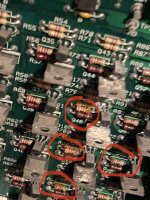
Since I got this game I noticed that a couple of my back box flashers were not working (circled in red below) ...and yes I know there are no bulbs in the sockets in the photo 😁

11.jpg


In the test menu these are the flashers in question (BACKGLASS RAFT & BACKGLASS RIDERS)


1.jpg 2.jpg


I traced the wires back and they connect to J128. It looks like J128 is solely responsible for these two particular flashers.

Here's the badger:

IMG_1732.jpg 111.jpg

Using my DMM I checked continuity from the Molex connector to the lamp holders and they checked out fine so no breaks in the wiring. I also changed the Molex connector for good measure but no dice they are still not working.

All other flashers in the backbox and the playfield work fine and these two flashers share the same voltage connection as some of those other flashers (J106-5)

Therefore I assume it is either a cracked solder joint on J128 header pins, a broken trace or another component further upstream responsible for these two flashers.

The Solenoid/Flasher Table lists them as:

SOL No 15
Backglass Raft
Low Power
Drive Transistor Q46

SOL No 16
Backglass Riders
Low Power
Drive Transistor Q44


I've tried to include as much information as I can. I'm just looking for a technical guru to help me and chime in with any other simple tests that I might be able to perform to isolate the problem further upstream before I go pulling the board.

Thank you :)
 
Just checked Q44 and Q46 should be TIP 102

Testing a TIP-102 transistor

Set the DMM to diode check
Place the black lead on the center leg
Place the red lead on each of the flanking legs in turn
A measurement between .5 and .7 should be displayed
Readings outside of this range (generally dead shorts) indicate the part has failed.
 
Game off, no power whilst doing this.
So rather than touch the legs as they were hard to get at I followed the guide and touched the ground plate with the black lead and the transistor metal tab with the red lead and there was no short.
 
Though there are some toasty looking resistors in that area...
 

Attachments

  • 85B3BD27-47C1-497B-8182-ED44DDB7D6DA.jpeg
    85B3BD27-47C1-497B-8182-ED44DDB7D6DA.jpeg
    126.6 KB · Views: 20
The tab is the quick test to ensure that any solenoids powered by the TIP won’t stay on and burn out but the legs give the better story.
 
Maybe, R72 and R78 are associated resistors but get a positive on the TIP first.
 
Interesting J127-7 and J128-3 are connected to the same TIP, which looks like a playfield coil. Are all the coils working?
 
Ignore that, testing my machine J127-8 goes to J128-3 and those are not used on J127-8
 
Q44 looks like an issue.
Do you have a spare tip 122 to replace it with?

I’ll order some.

So Q44 will be PART of the issue (for “BACKGLASS RIDERS” at least anyway)

What other components are in the circuit for these flashers to test next?

Did you see the photo of the toasty resistors in the same area:

A48C5FAD-1C10-4CB1-B3EF-264A8D125A22.jpeg
 
I have included the schematics. Page 7 left hand side. It is always worth just testing something that is working to get a reasonable reading and checking the schematics are not wrong or hard to read.

My motto is to test everything and replace only that which tests wrong and wrong against something that is working. Check those resistors and see if they give a different reading to others that should be the same as they are unlikely to give a clear 2.7k whilst connected to the circuit.

R80 is for Q48, which is the centre jet bumper based on my operators manual, can you check if that works?
 

Attachments

  • Williams_WPC_Schematics_Revised_May_17_1993_.pdf
    1.7 MB · Views: 4
I have included the schematics. Page 7 left hand side. It is always worth just testing something that is working to get a reasonable reading and checking the schematics are not wrong or hard to read.

My motto is to test everything and replace only that which tests wrong and wrong against something that is working. Check those resistors and see if they give a different reading to others that should be the same as they are unlikely to give a clear 2.7k whilst connected to the circuit.

R80 is for Q48, which is the centre jet bumper based on my operators manual, can you check if that works?

I was just looking at the manual myself and thought the same thing about the jet bumper. I’m pretty sure it works which is surprising considering the state of that resistor.
I think I already have some 2.7k resistors but if not I’ll add a bunch of 2.7k resistors to the shopping list.

R76 looks mega toasted so I have a feeling that Q44 might be the reason for ‘BACKGLASS RIDERS flasher not working and R76 might be the reason ‘BACKGLASS RAFT isn’t working’

I’ll replace all of the toasted resistors and Q44.

Is there anything else further upstream that might be at fault or do you think we are focussing on the problem area? Last thing I want to do is to replace these parts and they instantly smoke up.
 
TIP's are cheap, and flashers are too. If you have checked that the flashers are not shorting, then I wouldn't be too worried replacing one I knew was faulty.
What readings did you get on R76 compared to R80?

Sorry to ask, have you replaced components on boards before, they can be a bit delicate?
 
TIP's are cheap, and flashers are too. If you have checked that the flashers are not shorting, then I wouldn't be too worried replacing one I knew was faulty.
What readings did you get on R76 compared to R80?

Sorry to ask, have you replaced components on boards before, they can be a bit delicate?

I’ve not tested the resistors but as they are burnt I’ll just replace them as I’ll have to remove to test properly anyway.

I’ve done a little bit of board work before on my arcade games so have replaced caps, transistors and resistors before. My most recent repair was replacing a 555 timer which was my first IC replacement and that went fine. I have a desoldering station which helps.
 
A lot of evidence of water/moisture (condensation?) ingress on the board which probably caused shorting. I'd clean the tracks on both sides of the board with IPA if possible.
 
Sounds like you know what you are taking on.
Good luck and let us know how it goes.

Parts ordered. I’ll remove the parts and clean up the board with some isopropyl before installing the new parts. I’ll report back (might be a week or two)
 
You need to check the obvious first before jumping in on board repairs
You may have continuity on the wires but if you have no voltage then you ain’t going to get a flash
 
As in the red-white wire should be supplying the 20v to the bulb holder (and bulb) before the transistors operate to enable the flash (through the brown-violet and brown-grey wires).
 
Pretty sure I covered that in one of my replies when I said:

“All other flashers in the backbox work fine and these two flashers share the same voltage connection as those flashers (J106-5)”

Therefore if the other flashers work then I must have voltage on that red-white cable.
 
Therefore if the other flashers work then I must have voltage on that red-white cable.

Not necessarily... if the none working lights are at the end of the row and there's a break earlier in the row between those that work and those that don't...
 
Not necessarily... if the none working lights are at the end of the row and there's a break earlier in the row between those that work and those that don't...
I’m pretty confident there are no breaks but I’ll double check continuity on the red-white wire between a non working lamp holder and a working one just to make sure. Thanks
 
I just want to double check ahead of receiving these parts if there is anything else specific to this particular circuit for these two flashers that could have taken out the resistors / transistor that I could check when I get the board out?

Just trying to avoid chasing my tail and replacing parts only for them to blow again as it’s a bit of a faff to keep taking the driver board in and out not to mention the risk associated every time we desolder / solder in a part.


4E595F9C-EE78-4645-966D-517625E4B4AD.jpeg
 
Last edited:
Back
Top Bottom