printkid
Registered
what a transformation first class job
what a transformation first class job

 Since then finished nitro ground shaker and added to SWL line up, commissioned FG and TFTC into the SWL line up, a couple of Haunted House playfield swaps, work in progress with a BSD and now Firepower. I shall return to Space Shuttle in a month or two..!
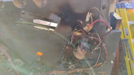
Hi Peter, When you get back onto this check that you have +12V on pin 19 and -5V on pin 21 of the EPROMS. I've just seen my third CPU board with these missing for the same reason. There are two plated through holes both at the bottom right corner of the rectangular silk screen markings for the original battery, above Pin 24 of IC5, which seem to be the first bit that gets affected by any battery corrosion and these plated through holes go open circuit cutting off these supplies to the ROMs.Fitted the new ROMs last week, unfortunately to no avail so the game got folded again. Last Sunday I did some homework on the MPU circuit diagram to identify which chips to check on next, which I'll do when I get the game set-up next. Going to be a detailed oscilloscope job trying to trace the fault.
Hi Peter, When you get back onto this check that you have +12V on pin 19 and -5V on pin 21 of the EPROMS. I've just seen my third CPU board with these missing for the same reason. There are two plated through holes both at the bottom right corner of the rectangular silk screen markings for the original battery, above Pin 24 of IC5, which seem to be the first bit that gets affected by any battery corrosion and these plated through holes go open circuit cutting off these supplies to the ROMs.

No problem, on it's way.Yes, it may well be and I think that it would be a very big help (if only to rule out what is and isn't working). It is most kind of you to offer and I would like to accept, PM sent.
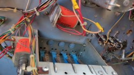
 Any how I was passing @Zaccaria Keith at the weekend and was able to leave the board with him to test in his working game. I got a lot more than I bargained for (as did Keith)...
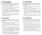
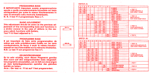
If it helps, here is a link to the DIP switch settings for the programming board.
http://www.zaccaria-pinball.com/gen1/misc.html

If your backbox is missing the labels you can print off the attached which are scruffy enough to look original!I have the info, thanks. Keith programmed it so I don't have to worry about it any longer.
Check myone thanLooking forward to thisPeter, that is one of the roughest looking Zacc's I've ever seen
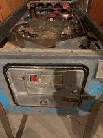
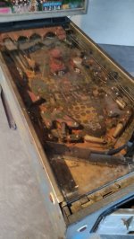
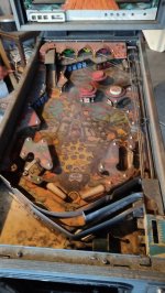
Does anyone sell Novus by the gallon?Check myone than
Quick wipe over and a couple of new fuses I reckon....Check myone than
Just come across this threadPack holes with wood glue (no nails) and bits of wood then let dry...
View attachment 116771
I ought to mention that it took the best part of 2.5 hours to remove the three sheared threads, taking it steady so I didn't do too much damage.
Then on to gluing the new number 5 insert in to place (no picture).
Then on to sorting out the shooter rod and it's very mushroomed end...
View attachment 116772
First cut away the old rubber...
View attachment 116773
Put a metal filings catch tray underneath...
View attachment 116774
Then reach for the trusty wizard and grind off the mushroom like this (wizard inactive for this photo)... Always use eye protection when using power tools...!
View attachment 116775
Then remove cir-clip... Always cover with hand to stop them flying off in to the distance never to be seen again...
View attachment 116776
Store safely and easy to find again...
View attachment 116777
I then cleaned it up only to find that it was about 3 or 4mm shorter than it should be due to the mushroom so replaced it with a used stern shooter rod. I normally like to replace the spring with a nice shiny new one but I'm totally out of those.
Also clean the holder while the shooter rod is out... No shooter sleeve here.
View attachment 116778
View attachment 116779
Finished item...
View attachment 116780
View attachment 116781


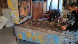
 That's going to take a while to sort out!