What's new
Pinball info

Register a free account today to become a member! Once signed in, you'll be able to participate on this site by adding your own topics and posts, as well as connect with other members through your own private inbox!

WPC 89 cpu switch issue

Wintonmartin

Registered
5Years
Joined
Mar 28, 2020
Messages
443
Location
Formby
Seems the fish tales I recently picked up is being a bit doolally so thought I'd have a bash at checking the board and replacing any acid damaged components.

I've never used a logic probe before but fine with a DMM. I've watched a few videos and it seems straight forward. Its something I've got to learn in this hobby.

Does anyone have any tips for using a logic probe or testing on a WPC 89?

I've not managed to test through the switch tests. I changed some headers on the PDB and got 2 connectors mixed up and blew C11 🥴 so it's off for the time being.

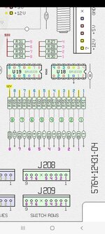
I got these labelled board layouts from pinside to help.
 

Attachments

What is going wrong exactly? Logic probe will not necessarily help you identifying single switch issues e.g. If the CPU is seriously acid damaged you need to fix that first one way or another.
 
Seems the fish tales I recently picked up is being a bit doolally so thought I'd have a bash at checking the board and replacing any acid damaged components.

I've never used a logic probe before but fine with a DMM. I've watched a few videos and it seems straight forward. Its something I've got to learn in this hobby.

Does anyone have any tips for using a logic probe or testing on a WPC 89?

I've not managed to test through the switch tests. I changed some headers on the PDB and got 2 connectors mixed up and blew C11 🥴 so it's off for the time being.

I got these labelled board layouts from pinside to help.

Ah the old J124/J132trap that Williams set for the unwary . Been there done that , wrote the thread 😂

 
What is going wrong exactly? Logic probe will not necessarily help you identifying single switch issues e.g. If the CPU is seriously acid damaged you need to fix that first one way or another.
A few of the switches weren't registering. Looking in the manual they were related to u18/19/20 so wanted to test the ICs first. A bit of a training exercise I suppose without causing any damage.
I've ordered some spare bits that were affected like resistors, sockets and ICs.

Ah the old J124/J132trap that Williams set for the unwary . Been there done that , wrote the thread 😂


I had to remove the head to get it out of the guys house and took looks of pictures. I was really careful putting it back when I got home but after the header repair I'd had a bit of Dutch courage and balls it up. Luckily It didn't burst. I've ordered a few replacements in case it happens again 🙃
 
A few of the switches weren't registering. Looking in the manual they were related to u18/19/20 so wanted to test the ICs first. A bit of a training exercise I suppose without causing any damage.
I've ordered some spare bits that were affected like resistors, sockets and ICs.


I had to remove the head to get it out of the guys house and took looks of pictures. I was really careful putting it back when I got home but after the header repair I'd had a bit of Dutch courage and balls it up. Luckily It didn't burst. I've ordered a few replacements in case it happens again 🙃
We’ve all done it , or similar. This wasn’t quite my messiest smoky horror show of my own making …. But that’s a story for another day 😂

All fun and games and you only do it once (hopefully) 😁
 
On switches: If a column or row is broken all switches on that won't work - easiest way to figure this out is to disconnect J207 and J209, go into switch test and then connect one of the columns to all of the rows and vice versa with a cable - you should always only get one switch lit at all times. If multiple ones come on/none come on you have a problem in the associated chip. No probe needed ;-)... Provided this works and operating the switches doesn't you have an issue with the cables or diodes on the switches.
 
We’ve all done it , or similar. This wasn’t quite my messiest smoky horror show of my own making …. But that’s a story for another day 😂

All fun and games and you only do it once (hopefully) 😁
Replaced and connected back up. All OK
Really annoying that the cable length is made to fit J132. Maybe someone at the williams factory did it for a laugh.

On switches: If a column or row is broken all switches on that won't work - easiest way to figure this out is to disconnect J207 and J209, go into switch test and then connect one of the columns to all of the rows and vice versa with a cable - you should always only get one switch lit at all times. If multiple ones come on/none come on you have a problem in the associated chip. No probe needed ;-)... Provided this works and operating the switches doesn't you have an issue with the cables or diodes on the switches.

Nice one for the advice. I'm gonna go through the switch matrix thoroughly now it's up and running. I replaced the acid damaged chips and resistors as wanted to clean the board up (although my soldering is questionable) so thought that may resolve it but still getting the same issues
 
OK so I've run through the switch rows and columns and all fine apart from switch row 8 which is completely down.
Manual says its fed from U19 leg 7. I've tested continuity from the jumper pin up to leg 7 and tested the components in-between. All OK
I've tested leg 7 with the logic probe and all tests fine too (new socket and IC)

Any advice on where to go from here?
 
Screenshot_20220319-131950_Acrobat for Samsung.jpg

I've probed 1-7 on the 74LS240 and getting a high reading. Completely dead on 8. Would it be a bad 74LS or further up?
 
Switch row 8 is U19 pin 5? that outputs to pin 2 of U19 -put your logic probe on pin 2 - test with all switches open on row 8 - should be hight and then close a switch on row 2 and see it start to buzz.
 
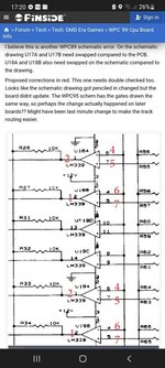
I've not been using the schematics yet but pulled this from pinside that someone did. Have I been down a rabbit hole?

Screenshot_20220319-142131_Acrobat for Samsung.jpg
 
I've just gone back to the pinside thread to be sure as when following the traces it leads back to leg 7 so the schematics are incorrect 🤦

I tested on pin 1 for the output with the probe and I get a slightly higher pitched noise from the probe. Same when testing pin 7. Does this mean its outputting correctly?

Screenshot_20220319-172000_Chrome.jpg
 
I've just gone back to the pinside thread to be sure as when following the traces it leads back to leg 7 so the schematics are incorrect 🤦
So the coloured pinside diagram is correct and the schematics are wrong? (I think I used the coloured version myself when I was troubleshooting a board a couple of years ago.)
 
Seems so. I'm a noob and can barely read schematics so the coloured one seemed to help until I compared it then I lost my head.

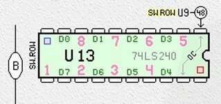
The output on pin 1 u19 leads to pin 8 on u13. I'm not getting any reading on pin 8 so there's a break Inbetween?

I'm not sure what's inbetween as i can't seem follow the traces.
 
Ok right, so schematics incorrect - that's a pain!

if U19 pin 1 is the output for row 8 and it is oscillating between high and low (with a row 8 switch closed) then that's working correctly.

use your multimeter on continuity test to check that the two pins on the 2 chips are connected. Given there are schematic errors, might be worth checking some of the other connections between U19 and U13 - there are 4 circuits - for rows 5,6,7,8 - so check them all as you know 5,6,7 are working, see if you can spot the difference between the working ones and the non working row 8.
 
Im not suprised theres an error in the schematics as usually a few in the manual.

Did some checking on the board. Think I've found it.

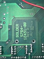
The traces from the 10k resistors flip to the other side of the board but on the parts side they run underneath the resistors so hard to follow.

20220319_180510.jpg
 
and have you got continuity between the 2 pins on those 2 ICs for the row 8 circuit? if not then you e got a broken trace. if they are connected then what is the output of u13 doing?
 
and have you got continuity between the 2 pins on those 2 ICs for the row 8 circuit? if not then you e got a broken trace. if they are connected then what is the output of u13 doing?
I have now. Soldering a wire across and all testing fine.

Thanks for the help.

Probably could've found that a little easier looking at it now but first time for switch/board fault finding.

Good to know my replacement IC sockets turned out to be ok.

Fingers crossed for when I power it up
 
Don't forget you can shine a strong light on the other side of the board to help you follow the traces. Good luck when you fire up, God I hate the traces on WPC boards.
 
Don't forget you can shine a strong light on the other side of the board to help you follow the traces. Good luck when you fire up, God I hate the traces on WPC boards.
Great shout.

All fired up fine. Switch test is 100%. Had an issue with the GI after I changed the header but all sorted and playing well.

Ordered some comets and rubbers
 
Back
Top Bottom