What's new
Pinball info

Register a free account today to become a member! Once signed in, you'll be able to participate on this site by adding your own topics and posts, as well as connect with other members through your own private inbox!

WMS Indiana Jones J120 and J121 female connector help needed

Baza

Registered
5Years
Joined
Sep 6, 2016
Messages
76
Location
Loughton
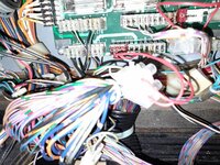
I have finally found a Williams Indiana Jones and bought it because of the great condition of the playfield but it does have a lot of small issues that I am gradually working through one by one. I have sorted out a lot of the issues but am left with a few one being that the top box 2 rows of lights have issues. None of the 2 rows of standard #555 bulbs were working. I have found that whoever fixed things on it before had somehow broken the J120 and J121 female connectors and has rather than replace them left the snapped bits on and just added some type of smaller red connectors on the end to connect the wires too. They are pretty loose and when I fiddled with them the bottom rows of back box lights come on, but not the top rows.

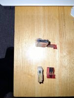
I have two new 11 pin female connectors and will replace them no problem, but he has also for whatever reason has broken 4 wires that come in to these 2 connectors and added connector blocks about 6 inches away and put red wires off of them into the broken female 11 pin female J120 and J121. I will again tidy this up correctly.

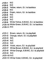
I have an awful feeling though that he may have connected one of the wires on to the wrong pin, maybe not but I would like to ask a favour of any one that has an WMS Indiana Jones if possible, would someone be able to take a picture when you have a moment free of the wires that go into and the connectors of J120 and J121 for me so I can see where each colour goes in to what pin on them so I can make sure that mine are all chroned in to the new 11 pin female connectors when I replace them.

cheers Baz
 
Hi Baza,

I don't own an IJ, but I will say that the wiring loom is colour coded and also the correct wiring (wires) will be listed in the IJ Manual.

If you get a pdf version on your computer, it would be easy to scan through page by page until you find what your looking for.

It will be easy for you to confirm you're looking at the correct info because the wire colouring in your back box will (mostly) match your manual.

I am out tonight, but will look into it later or Monday if you want help. Send me a message if needed as a reminder. Although someone may reply sooner.
Hi Marcel

appreciate the quick response. the only thing I can find on it in the manual is on page 3-5 general illumination and I cannot see it aligning at all with what I have. I wonder if some one can send me a photo of theirs so I can compare as the manual doesnt add up on that page to any thing like mine and I have.
 
I would follow the pages referenced above, find something it should go to and check continuity before placing the pin in the connector box.
I actually go as fair as using an old loom given to me by @replicas, and splice in the right colour wires if I have to lengthen the existing damage. Helps me follow it in my head and properly fixes the bodges.
A lot of machines get hacked to keep them running. These are the lucky ones that made their ways to nice homes.
 
Have you got any photos? It's not difficult to make new connectors. I've done it a few times since learning how to crimp but it's knowing which wires go where that can be hard if someone's hacked it.

The red things you speak of sound like splice connectors? But photos will help!
 
It's on page 3-33 of the manual. 3 pages from the end.
Thanks Asiapinball, so I have all the connections the same but J121 has the connections to the pins in the book that J120 has and J121 has the connections to the pins of J120 in the book on that page. maybe I should just change the female connectors and get rid of the bodge job and see how it goes. be nice if some one has a photo of each of their connectors to show me but hey. It may all work out in the wash if I change the 11 pins out to new ones from the bodge up.
 
so I think just changing the bodge ups to new 11 pins may help but photo of the J121 at the bottom and J120 above
 

Attachments

  • 20220508_192453.jpg
    20220508_192453.jpg
    214.8 KB · Views: 36
so I think just changing the bodge ups to new 11 pins may help but photo of the J121 at the bottom and J120 above
as you can see the above J120 has a snapped femail connector with one ;lose red one added and the bottom J121 has a snapped female connector with a 3 red connector added that again is lose and both will be changed out to a new 11 pin.
 
Page 149 of 152 of the Indiana Jones - Power Driver Board J120 & J121
 

Attachments

  • IJ Wiring.jpg
    IJ Wiring.jpg
    84.8 KB · Views: 11
as Pick Holder said change the plugs and sockets, correct the wiring to original.
I can see a burnt bit of print below the fuse, once the board is out that needs to be cleaned up.
The plugs and sockets are a very common fault and I’ve seen these bodges many times.
 
Page 149 of 152 of the Indiana Jones - Power Driver Board J120
as Pick Holder said change the plugs and sockets, correct the wiring to original.
I can see a burnt bit of print below the fuse, once the board is out that needs to be cleaned up.
The plugs and sockets are a very common fault and I’ve seen these bodges many times.
thanks I never noticed that I will look into that tiny burn
 
Thanks Asiapinball, so I have all the connections the same but J121 has the connections to the pins in the book that J120 has and J121 has the connections to the pins of J120 in the book on that page. maybe I should just change the female connectors and get rid of the bodge job and see how it goes. be nice if some one has a photo of each of their connectors to show me but hey. It may all work out in the wash if I change the 11 pins out to new ones from the bodge up.
On the driver board j121 and j120 are parallel connections anyway so it doesn't matter if the connectors are interchanged. I guess yours were swapped over when installed which doesn't matter.
 
On the driver board j121 and j120 are parallel connections anyway so it doesn't matter if the connectors are interchanged. I guess yours were swapped over when installed which doesn't matter.
now that makes sense if they are parallel. I will change them out and take a look at that little burn. Hopefully that will sort this out
 
so wish to thank every one for their help on this. All the back box lights now work. I removed J120 and J121 and the boidge up extra's and on the other side of the 11 pin connectors was actually written the J120 and J121 numbers in pen, which were not only bodged up but had been placed back on the where the other should have been i.e. J121 was on J120 and vice versa. I have replaced both of the female 11 pin connectors and placed on their correct pins and all the back box lights now work. I have added a photo of the ones I pulled off and really for £2.50 each why any one would do what the did when you see the broken ones and the crappy loose extra ones added to them I will never know!!!!
 

Attachments

  • 20220509_162453.jpg
    20220509_162453.jpg
    90.4 KB · Views: 22
Back
Top Bottom