What's new
Pinball info

Register a free account today to become a member! Once signed in, you'll be able to participate on this site by adding your own topics and posts, as well as connect with other members through your own private inbox!

Wanted Williams System 11c interconnect board

cooldan

i like pizza
10 Years
Joined
Jul 21, 2011
Messages
7,097
Location
Ealing, London
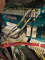
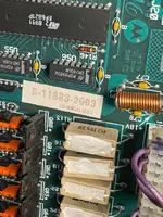
apparently there were two different versions of this, and mine is the 'wrong' one for my CPU board (on Rollergames).
Has anyone got one that can tell me about it and maybe sell me it or teach me how to adapt the one i've got?

thank you

gif excuse me ladies it's Rollergames pinball Yay.gif
 
 
So.. i may be wrong here... however the interconnect board seems correct for the machine... the only mismatch is the cpu - and from memory the last three digits (-576/-2003) just means its the same board, however just originally used in a different machine (-2003 is Bally Gameshow, -576 is Rollergames)
 
So.. i may be wrong here... however the interconnect board seems correct for the machine... the only mismatch is the cpu - and from memory the last three digits (-576/-2003) just means its the same board, however just originally used in a different machine (-2003 is Bally Gameshow, -576 is Rollergames)
Wouldn't it be easier (and cheaper!) to find another correctly matching interconnect board than a correctly matching MPU...? or is it a case that no interconnects are capable of matching that MPU and that Dan needs the correct MPU?
 
As far as i can tell (and i have no practical experience of RG) they are both correct...

1736182006115.webp


So in theory if you have a D-11883-xxx MPU, a D-12313-xxx Interconnect, and a D-11581-xxx Audio board then that should be correct. if i take the one for Gameshow (as an example)...

1736182095661.webp


The MPU, the Interconnect board, the sound board and the Aux power board are the same.... which makes sense... These are all System11C MPU's

1736183920670.webp
 
Wouldn't it be easier (and cheaper!) to find another correctly matching interconnect board than a correctly matching MPU...? or is it a case that no interconnects are capable of matching that MPU and that Dan needs the correct MPU?
I actually dont think there's an issue with what Dan has there revision-wise!!
 
Dan,

I think you need to get back on track with what @Moonraker was leading you through.

From what you originally described you have problems with flashers not working or blowing or flashing on the wrong circuits. Most likely problem is on the interconnect board or shorts in the wiring and as @Moonraker stated in an earlier.post if there are say 3 flashers on the same circuit and 2 of the bulbs are blown the 3 bulb will blow in short order.

All the interconnect boards across games are the same construction other than the resistors that are installed on the board. Confusingly RG had 2 versions of the interconnect board as early games had flashers in the backbox insert. So you need to determine whether your game had flashers in the backbox insert and that will then tell us the resistors you should have and then you can determine whether you have the correct interconnect board.

But given that you have described one flasher circuit flashing lamps on another circuit I suspect you have a short in the wiring and it's nothing to do with the interconnect board. You need to find the short first.

Here is a useful write up from pinside o similar problem.

 
The thread I linked to on pinside has a listing of what the resistors should be for the early games with the flashers in the backbox as per the manual and what the resistors should be for later games without the backbox flashers. The manual is only correct for the earlier games with backbox flashers.
 
Thanks I’ll have a read. Mine is one of the early games (they made them from April to December and mine is late April) so it has the holes drilled for backglass flashers but no wiring.

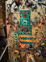
I think I know how to check for shorts but am not certain - am I correct that there should be continuity between all flashers, both sides? Even though they have differing (black/xxx) ground wires? Is it not relevant that the 89 bulbs are ok but the 906s are all not ok? Why did the fuse on that interconnect board blow? And still on circuit Flash 1, which controls four flashers, the 89 works but the three 906s don’t - how is that even possible?
IMG_6596.webp IMG_6595.webp

When I was under that top ramp there was not continuity despite a new bulb across this one (black/blue) so I reflowed that solder.
IMG_6727.webp
 
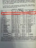
OK, so you have a later game that doesn't have backbox flashers so what is stated in the manual for the interconnect board resistors is not correct. Cutting from the pinside thread I linked to above the resistors you should have on the interconnect board are:

For the record, here's how those resistors seem to rate on this non-prototype machine (no flashers in the backbox). They're all 5 watt.

R1 = 3 ohm
R2 = 4 ohm
R3 = 11 ohm
R4 = 11 ohm
R5 = 5.6 ohm
R6 = 11 ohm
R7 = 11 ohm
R8 = 4 ohm
R9 = 11 ohm

Clearly, those do not match the manual.


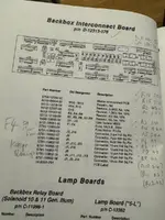
So, if your resistors on the board match these you have the correct resistors on the interconnect board. I think you do as you scanned a pic of the manual page with resistor values all hand written and they all closely match the values as above (R1 and R2 are a bit out of specification, but should be OK).

So I don't think your interconnect board is the issue.

More to follow....
 
These are the values I got when I measured the resistors yesterday
IMG_6676.webp

so my numbers are all correct
 
906 bulbs and their holders often lack continuity due to small amount of corrosion either on the small wires on the bulb itself or on the brass holder contacts. Many people just replace the old black twist in holders with new but otherwise you van revive them with a folded up piece 600 or 400 grit sandpaper. You should pit a bulb in the holder and the test for continuity across the bulb and holder together before twisting it into its pcb. Next issue is the pcb itself. Over the years you get divots where the holder is making contact with the solder pad on the pcb and these divots lose their conductivity. You can twist the holder a little off the divot and it will then work better.
These are the values I got when I measured the resistors yesterday
View attachment 269015
so my numbers are all correct
Yes - they look correct for Rollergames without the backbox flashers so all good there.
 
Or for a bit better fix than just twisting the holder a bit off the divots you can reflow the solder on the pads, adding a little more fresh solder to make it flow easier.

So all that should sort out the continuity issues with your 906 lamps and their holders and their pcbs.

And the #89 bulbs and their holders are a little more robust. There are no tiny wires on the #89 bulbs and the holders have better contact with their bulbs. But whenever I refurb a machine I will use a small wire brush on my dremel to give the connectors and the contacts on any lamps I am reusing (I prefer original incandescent to LEDs) a quick clean up where they contact each other so that you get good continuity.

This probably explains why your 89s work but your 906s don't on the same circuit - the 906's have continuity issues around the lamps as they have corroded/divoted.

More to follow...
 
So how can one lamp work and not others. Its simple - on System 11 the flasher lamps are in parallel not series. If they were in series then one blown lamp means non will work. In parallel the remaining lamps will continue to function.

But as @Moonraker pointed out if one lamp blows then the others have to share its load so they will quickly blow when one of the 3 or 4 that are in the same circuit has blown. So you need to make sure they are all working properly and replace any that blow as soon as you notice. i.e. every lamp neds to be working at all times or you will just blow the others.

More to follow...
 
thanks Paul, i'm totally grokking out on all this techy knowledge, i *really* want to learn and understand this stuff better, it's kind of a goal of mine for when i retire
 
You can't test the continuity across a lamp that is in parallel with others when it is in circuit. If any of the lamps are working then you will get continuity, because you have continuity across the working ones. If you have 4 lamps in a parallel circuit you will need to remove all but one, test that is ok, then remove it and put the next one in and test, and so on until you have done all 4. If all OK, then you can put them all back in and you know all will be working.
 
thanks Paul, i'm totally grokking out on all this techy knowledge, i *really* want to learn and understand this stuff better, it's kind of a goal of mine for when i retire
I'm trying to keep in bite size chunks for you. Just don't go working on this now if you have had a few sherberts :)
 
you know me. yes, i have had a couple of minor drinkies, but am still following along - i tend to make it a bendable rule not to prod the live circuitry while inebriated. in any case, this will have to wait a couple of weeks as i'm about to head off for some me-time.
 
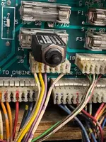
And one thing that did occur to me - just check you have the connectors on the interconnect board in the right place and not off by a pin or two. J11 and J12 look really easy to mix up - maybe there isn't even a connector at J11 as there are no backbox flashers. Mixing up connectors or having them off by a pin causes all sorts of issues of the sort you describe.

Finding a short elsewhere is a much harder task and often as much visual as testing - best place to look first is usually where a previous owner has bodged something.

But overall, I expect much of your issues are continuity issues probably around the lamps and their holders of this 37 year old machine.

I love Rollergames - I don't have one but its on my wishlist :cool:
 
Is the game working fine with the current interconnect board ? If so what’s the problem ? Just leave it.
It’s working 95% Ive but you know me, I’m very precise, quite detail-oriented, bit of a nerd, complete dickhead. I actually quite enjoy this stuff, chasing bugs, learning new skills.
 
on System 11 the flasher lamps are in parallel not series. If they were in series then one blown lamp means non will work. In parallel the remaining lamps will continue to function.

It's not applicable for RG, but the early System 11 games did have their flashbulbs wired in series. Pin-Bot, f'r instance, has circuits with one lamp on the playfield and the other in the 'light bar' topper. While F-14, the last of the S 11 games to use series wiring, has the six lamps behind the Launch wireform at the back of the playfield paired with six others around the playfield, in a clockwise sequence.

Williams first game with flashbulbs in parallel, Fire, had an appetite for No. 89 lamps. This seems to have been due to the resistor values still being suitable for series wiring, i.e. too low. I bumped the value up a little; the lamps didn't show so well in the test mode, but weren't too badly affected during play, and lasted longer.
 
Last edited:
Back
Top Bottom