Pinball info
You are using an out of date browser. It may not display this or other websites correctly.
You should upgrade or use an alternative browser.
You should upgrade or use an alternative browser.
WCS board
- Thread starter jonathan
- Start date
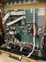
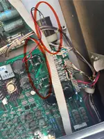
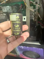
8 diodes have replaced the bridge recifier and the capacitor fitted externally to bypass the 2 board fitted smoothing caps by the looks
Is that a reasonable fix or a bodge? Ie: do I need to fix it?
Not seen it done before but those diodes are beefy! Maybe someone else can advise better8 diodes have replaced the bridge recifier and the capacitor fitted externally to bypass the 2 board fitted smoothing caps by the looks
Purely from a logical point of view, the elctrons probably see exactly the same path and if your 5V digital is fine, then you are fine.
The top quartet are for 5V digital and the bottom are for 12V digital. TP2 should be 5VDC exact,TP8 gives 18VDC before the voltage regulator drops that down to the 12VDC at TP3. If they are good, then the setup is good.
Looks like your voltage regulator is the orignal type, and if you MPU boots, it is all doing its job.
Those diodes are doing the same the bridges. But I would remove that extra capacitor and replace the C5. And check if the C4 and C31 are the original ones and replace those too.
Ooofffff that’s a mega bodge and looks horrible go back to standard the original way


