What's new
Pinball info

Register a free account today to become a member! Once signed in, you'll be able to participate on this site by adding your own topics and posts, as well as connect with other members through your own private inbox!

vector flippers

rockhouse

Registered
5Years
Joined
Jul 10, 2015
Messages
393
Location
essex
further adventures in a non working vector
so far got all lights working:clap:
replaced parts in high voltage section on solenoid board, displays now working:clap:
all solenoids now fire in attract mode :clap:

thats the good part, now the:( part no flippers
i have 41 volts on all lugs on lower flippers
40 volts on upper flippers
j1-8- 40 volts
j1-9- 40 volts
j2-1-zero volts
j2-2-zero volts
put new molex male and female connectors on the solenoid board still no volts on j2- 1 and 2
if i ground q15 the relay on solenoid board works
and the relay in solenoid test mode pulls in
the soldering is terrible not mine how i got it:eek:
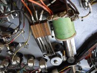
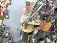
a couple of pics of lower flippersSDC13936.JPG SDC13937.JPG
 
Last edited:
j2-1-zero volts
j2-2-zero volts

Is that A3J2-1 and A3J2-2...? if so then they'll be nothing until you press the flipper button... or is that what you were trying to say anyway? :hmm:

What do you have at A2J2-2 as that feeds the flipper buttons...? Note feed is from board A2 (transformer power module) and not A3.

Is TP1 showing 6.5v on A2?
 
a3 j1 and a3 j2 on voltage regulator/solenoid driver board
a2 tp2 150 volts
a2 tp1 7 vdc
 
Huh, just looked again and you're right, you need voltage on A3J2-1 & J2-2 rather than A2J2-2 (which is the path to earth to fire the coils once the flipper button has been pressed).

Looks like you need to concentrate on the flipper enable relay on A3 (as seen in the top RH corner of page 52/59 in the pdf). Or the path to/from the relay. With power on do you have 43v at either leg of CR20 on A3 (it's the diode under J1 and above the relay) ?
 
Next question (!) is the relay energising when it has 43v on it...? If not then it looks like you might need to replace the relay to get power on the flippers. If it is then you need to take the board out and check the tracks from the relay to the connector J2 (perhaps reflow solder for the relay and connector).
 
if i ground q15 the relay on solenoid board works
and the relay in solenoid test mode pulls in
i just wonder if the wires on the flipper coils are right anyone got a pic
of vector flippers
 
Hi,

With the pre-WMS Bally flipper units, the wiring is arranged so that each lower flipper pulls-in when the button is pressed, and in addition to opening its EoS switch, closes another pair of contacts to operate the upper flipper. The Stern games of the time used the same method. There may be nothing at all amiss with the upper flippers - have you tried holding a lower flipper paddle in the raised position and pressing the button (with the relay energised)?. This assumes that the relay's good, though.

Re. the coil wiring; I've been scolded before, so I especially remember that with Bally flipper coils, the 'front' end of the coil (with live power applied, which is the side terminal with the banded end of a diode - White-black & 2x Brown in the first pic) is the start of the hold winding. The junction between this and the power winding is the middle terminal, so the normally closed EoS switch should be wired across these two terminals, to short-circuit the hold winding while the switch is closed. The 'tail' end of the coil (the other side terminal, with plain end of a diode) heads off to the button and then finally to Ground via one pair of the relay contacts (or is it the other way round, i.e. relay then button?).

Looking at the first pic, the White-black on the EoS switch looks suspicious - I'd expect a pair of Brown wires, like the second pic. Though it looks like the White-black does loop round onto the switch.

The crude technique of using a jumper wire to by-pass wiring & contacts will work with a flipper coil; just make sure not to use it on the middle terminal. Grounding the tail end of a Bally flipper coil should energise it at any time the game is powered-up, not just with the relay On. Though it only shows if the coil and EoS are good, you can then follow the return wiring through connectors and board connecting pins right up to the 'proper' grounding point, either in the cabinet or the grounding for the Solenoid Driver board.
 
Last edited:
held left lower flipper up and pressed flipper button nothing
tried right flipper and same nothing.
will take a while to work the rest out;)
thanks for input appreciated:thumbs:
 
no question is silly
i havn't checked yet got to go out so will check later but any suggestions
feel free to add
thanks for help
 
when I had no right flippers on my vector,it turned out to be a dodgy connector on the solenoid driver board,have you checked the pins for dry joints?,failing that is there anyone local to you with a bally pin,who could test the board for you in a working machine?
 
a bit of an update if it helps anyone with the same problem:wave:
replaced male and female molex connectors on A3 solenoid/driver board, bit overkill
but the board was out so why not.
and the result was :clap::clap::clap:got 3 flippers and a new solenoid for the one that doesn't work.
next:tut: problem wont come off game over
thanks to all for help.
will start another thread for game over problem
 
Back
Top Bottom