What's new
Pinball info

Register a free account today to become a member! Once signed in, you'll be able to participate on this site by adding your own topics and posts, as well as connect with other members through your own private inbox!

Twilight Zone fuse F105 problem

Jonwolf

Registered
Joined
Apr 4, 2016
Messages
1,134
Location
Wolverhampton
I am a novice when it comes to pinball diagnosis so I am a bit lost on this:

My TZ reset itself yesterday and now F105 blows each time machine is powered up. Solenoids 1 to 8 don't work.

I have unplugged connector J107 and F105 no longer blows when powered up.

I have used a multimeter to test resistance of all coils in the machine - reading of at last 5 for all coils. It was the first time I've used a multimeter so I hope I got it right.

Visual inspection of coils reveals nothing (although I'm not sure what I'm looking for!)

Any advice would be appreciated - it's taken me ages to get absolutely nowhere.
 
A quick but dirty way to ascertain what your problem is this.

Sol 1-8 are all driven via j130. So remove this connector

Reinstate J107 and F105.

Power on. Fuse should not blow as solenoids disconnected at J130.

Now offer up J130 but don't push it on. One of the connections will spark as you connect the short circuit.

This will identify your problem based on the number of the pin sparking at J130.

But now you'll have to check out the relevant coil, and replace the driving transistor on the circuit board and possibly components prior to this
 
Thanks, The board is currently at Pinball Heaven - been tested and it wasn't a board problem. If I do the J130 thing, will it damage anything on the board?

I was thinking I could also measure the resistance from J107-3 to each of the pins on J130 - would that tell me anything ?

This steep learning curve is almost vertical !


Sent from my iPad using Tapatalk
 
The board has returned by post and I am fitting it. I took photos of where the connectors go so all good - NOT!

My photos clearly show that J138 was used and connector in place. When I look at the manga it says that J138 is NOT used and the connector goes in the slot above (J137)

Which is right ? The manual or where it was connected originally?

The machine worked ok with J138 - should I believe the manual or where my connector was ?
 
If you look at the board I expect you'll see that j137 and j138 are directly connected (check though, don't just take my word for it) meaning you can use either

They seem to have done that for some connectors on the switch matrix too. I guess it makes life easier for an operator, if one connector burns up just use the other inline.
 
I guessed as much - the J104 and J105 seem to be interchangeable too - thanks for the advice


Sent from my iPad using Tapatalk
 
Ok, so power board installed and I started the pain...

When powered up the fuse F105:

Blows when J107 and J130 connected
Blows when J107 connected and J130 disconnected
Doesn't blow when J130 connected and J107 disconnected

NOTE - blue flash on J107 when connected with power off

It's J107 !!!

The board is supposed not to be the problem as Pinball Heaven have checked it over, I thought maybe it was a transistor

So, a playfield problem. I have checked solenoids 1 to 8 with multimeter and all show at least 5
Visual checks reveal nothing although I'm not totally sure what I am looking for. All wires look look.

Should I do the offer up J107 and try to see the flash on which pin ?

Regards

Jon
 
Should I do the offer up J107 and try to see the flash on which pin ?
Don't think that would help. If you look at schematics you can see F105 is connected to pin 3 of J107, so we already know the issue is there. What's weird (going off what Andy said) is that you saw it blow with J107 connected and J130 disconnected.

It would mean you've got a ground short on the power to one of these 8 solenoids
Slot kickout
rocket kicker
autofire kicker
gumball popper
right ramp diverter
gumball diverter
knocker
outhole

I guess disconnecting the knocker is a simple enough test, I think it's usually molexed separately?

Until Andy comes back with some wisdom I might suggest disconnecting J107 and J130 and trying to see if you can buzz out a connection between one of the pins from the J107 connector lead (not the board, the lead that plugs into J107) and ground. If you get a buzz tone, that would help narrow it down

(I see you're a newbie, so by 'buzzing out a connection' I mean putting the meter into continuity testing mode where it emits a beep when there is a connection between the two meter terminals. Then put one meter lead against something connected to ground (such as the ground braid in the backbox) and press the other end against each pin of the J107 connector lead.
 
Last edited:
Ooooh!! Just remembered I've seen this before. In that case a winding of the knocker coil was worn through the paper winding, and making contact with the mounting bracket of the solenoid which in turn was in contact with the grounding braid. Try unplugging the knocker first and power on. Then minutely examine the gap between coil and mounting bracket. Furthermore check that the solder tabs of the coils are not contacting with any brackets.
 
Ooooh!! Just remembered I've seen this before. In that case a winding of the knocker coil was worn through the paper winding, and making contact with the mounting bracket of the solenoid which in turn was in contact with the grounding braid. Try unplugging the knocker first and power on. Then minutely examine the gap between coil and mounting bracket. Furthermore check that the solder tabs of the coils are not contacting with any brackets.

I had this on bsd on the auto shooter coil which had current going through the pf bracket and shorting on the lock down receiver to ages to figure it out
 
My multimeter doesn't have a continuity test but the internet says turn it to diode. A connection gives a reading of 0.

So I put black meter lead on braided grounding strip and then red lead in turn on each pin of lead connector J107.

Results:

J107-1: not used
J107-2: reading of 1
J107-3: reading of 0
J104-4: not used
J107-5: reading of 1
J107-6: reading of 1

As a newb I'm going to guess that in this case a reading of 0 is bad.

I disconnected the knocker and still got a reading of 0 on J107-3 so I assume the knocker is not the problem.

So, seven solenoids left to go.

I'll give the remaining ones another visual check in daylight tomorrow based on above advice - paying particular attention to wires touching brackets.

After that, I'm guessing that I need to desolder one of the connections (which one?) on successive coils and then test it as above. I'm guessing as soon as I don't get a zero reading on J107-3 then I've found the problem coil.

If someone can get back to me to make sure I'm not talking total crap I'd appreciate it ;-)

Enough for this evening - beer needed.

Thanks again guys


Sent from my iPad using Tapatalk
 
Your issue is that that wire (which I think should be Violet/Yellow), or like Andy says - one of the solder tabs on the coils it's connected to, has a connection to ground somewhere. If it's not a shorted coil it's possible a wire that has got pinched somewhere, or is worn through and now touching something metal. Could feasibly be anywhere on that length of wire between where you're testing it and those 8 solenoids it provides power to.

I would lift the playfield up, then do another test with your meter straight away - it could be that moving the playfield has released the pinched wire. If a good visual still doesn't show anything then you kind of want to start at 'the other end' of that wire, disconnecting that Violet/Yellow wire from each solenoid in turn and retesting
 
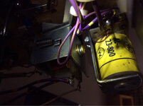
I have found the problem!!! It took all of two seconds to put it right. The copper wire exiting the auto fire coil was touching the bracket. You could actually see the tiny mark on the bracket made by the short.

A massive thanks to all you guys for the assistance and patience with a newb ;-)

One other thing - is it normal to feel such intense joy when a problem is fixed - a near bloody religious experience ! [emoji120]

Thanks chaps [emoji106]


Sent from my iPad using Tapatalk
 
One other thing - is it normal to feel such intense joy when a problem is fixed - a near bloody religious experience !
Yep, I feel the same. And the more you learn and the more you try and the more you achieve, it gets even better.

I recommend joining up to the Pinball Ninja and watching his videos. It costs $20 as a one off I think. He explains stuff brilliantly and makes you feel you can do it too .... drip drip drip the knowledge goes in and it's a real fillip, a real sense of achievement.
 
Ooooh!! Just remembered I've seen this before. In that case a winding of the knocker coil was worn through the paper winding, and making contact with the mounting bracket of the solenoid which in turn was in contact with the grounding braid. Try unplugging the knocker first and power on. Then minutely examine the gap between coil and mounting bracket. Furthermore check that the solder tabs of the coils are not contacting with any brackets.

If anyone has a Williams/Bally game, or a knocker from one, with insulating tape wrapped around the bracket, it's possible that the machine once belonged to my old workplace, since I did this as part of preparing new games.
 
Back
Top Bottom