What's new
Pinball info

Register a free account today to become a member! Once signed in, you'll be able to participate on this site by adding your own topics and posts, as well as connect with other members through your own private inbox!

Tron pro EL wire mods?

Rus121

Site Supporter
Joined
Jul 21, 2011
Messages
2,671
Location
Teesside
Anyone with the Tron pro machine attempted an EL wire mod for the ramps yet? I have seen a few people chatting about it over on rgp, but no pics of a finished product as of yet.


I think i would prefer Blue and yellow 'dual' wire mod attached via some clear vinyl tubing spliced down the middle in order to simply push onto the ramp edges. I got the idea from a thread on rgp after someone there suggested it first but am interested to see if someone here may have done it also...
 
Ive started to dabble with this on my PRO..

My current attempt is to put yellow el-wire on the back ramp (with the yellow bike), and indeed blue wire around the lip of the inner ramp (with the blue bike - duh!).

For the record, having measured both ramps with string, both seem to be just under 3 metres each in length.

I've fitted the blue wire so far (attached with sellotape for the time being whilst I try and work another very discrete way to attach it properly). However, I've not got a chance to attach the wire to the inverter that turns it on....

Talking of which, I've made a custom little breadboard that allows for 4 "inputs/signals" to each colour: these will be yellow upper and lower flashers, and then both of the ramp switches too. As Im presuming the flashers run on +20 and the ramp switches run on +5 Ive bought these vaqriable input voltage power pcbs that should havnlde each signal and output a clean +12 to flash the el-wire! So effectively, the el-wire should flash twice as the ball goes over the ramp and indeed whenever the ramp flashers trigger, which will be pretty cool with the end game sequence as thats all yellow and blue! I didnt want the el-wires to be on all the time of allot of the time so I'm hoping this approach will work well...


Belows a picture of the these assemblies: the breadboard has 4 inputs either side (dioded to not allow rogue voltages being passed between flashers and switches) to a 3 pin connector (red-black wire) that takes the signal into the voltage regulating pcb... The output of which goes into the black boxed inverters that fire the attached el-wire! Phew! All I need to do is make non-intrusive molex connections for flashers and switches and I can at least then see how effective it is (and make a youtube vid LOL).
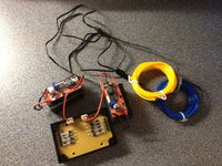


proel1-1.jpg


Do note though, that the el-wire is very yellow and blue even when un-illuminated (though the blue isnt that noticable currently) which is a bit fo a shame as I hoped it would turn out to be clear when unlit.


From google it seems LE's actually use fibre optic cable with a led illuminating the end - this will keep it clear when unfired and I might invest in a V2 version trying this....


Dunno if I'm doing it the best way! Be interested to hear peoples views - and indeed suggestions how to attach the cable without drilling holes!!!!


EDIT: a phew photos of the blue-EL sellotaped into place:
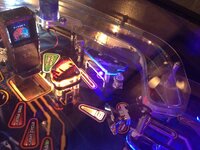
proel2-1.jpg


proel3-1.jpg
 
Wow. Looks like a well built mod there Rav. The Pro certainly is crying out for it. Cant wait to see yours up and running. Love that little Tron arcade mod too. Did you buy it as a kit?


Dont know if you have seen these before:

http://www.fiberopticproducts.com/Colormax2000.htm


That whole site has a lot of EL wire stuff and used with that colourmax thingy, would make an effect very close to that of the LE.
 
Nice link
smile-1.png
That colormax2000 looks ok, although my interpretation of the description is that its just sequential fast or slow colour changing and that you've no control over the clour it outputs... The first videos on youtube of the LEs did indeed look like this but I think a software update made the colours link to the game which would be far more preferential!
 
Thought someone had tried it and screwed up the machine? I don't think they'd done it this way though. I think the blue looks ok. Can't see a small hole though the return lip on the ramps mattering, this is how the light tubes are affixed on the LE anyway.
 
Can anyone find any info on how the machine may have got screwed up? I'm eventually going to play around with this too and don't want to kill things. I was considering fibre optic lit via an ultra brite LED in the end of it. I was actually thinking of two in a Y shape tube adapter. One yellow (or blue depending on ramp), the other, UV. Then use some kind of electronic wizardry to switch between the two.


All thoughts at the moment though. Too much else on my mind right now.
 
IIRC they had just tried to use the lamp matrix to turn on the EL wire, think this screwed up the power board. If I was to do it I'd use a roadshow shaker board and run the wire off that. This is how my Flash Gordon flasher is currently strobing....
 
Found a pic on rgp of a pro with the EL mod done quite nicely. Its been wired into the 12v outlet near the coin door and the owner states there are no issues doing it this way. Obviously it wont flash when you hit the ramp switches but you could use a sound activated inverter for the effect.


TronEL-1.jpg
 
Not mine, but someones over on pinside. Looks ok, but i think i prefer the yellow/blue look..... Now, time to get my hands on some of that EL stuff!
 
Back
Top Bottom