Pinball info
You are using an out of date browser. It may not display this or other websites correctly.
You should upgrade or use an alternative browser.
You should upgrade or use an alternative browser.
TOTAN Back Box Molex Wiring Connection
- Thread starter SeikoKid
- Start date
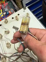
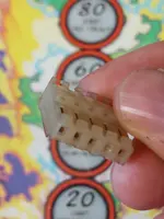
Which connector is it ?
Asiapinball
Site Supporter
Asiapinball
Site Supporter
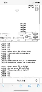
Just check the colours match what is in the manual as per page I snipped. Full manual download at ipdb.
Asiapinball
Site Supporter
You will need a 5 way .156" connector keyed at pin 4 for j114.
Asiapinball
Site Supporter
Asiapinball
Site Supporter
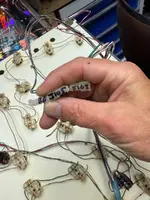
BB connector should be j134 a 5 way connector with single red and white wire at pin 5 but I can't see any of that in your pics.
Gentlemen. Many many thanks
Starting to understand how the diagrams etc are read now. On the pins i would expect 1-5 to be left to right but no, its right to left
So i also found the main molex had 2 cables snapped. Redid 108 with molex ( thanks Paul but no need at present )
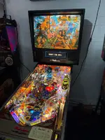
Now we are almost there with the fully serviced machine
Just waiting on some shiny new legs
Starting to understand how the diagrams etc are read now. On the pins i would expect 1-5 to be left to right but no, its right to left
So i also found the main molex had 2 cables snapped. Redid 108 with molex ( thanks Paul but no need at present )
Now we are almost there with the fully serviced machine
Just waiting on some shiny new legs
Attachments

Asiapinball
Site Supporter
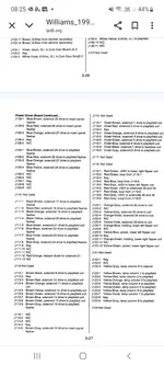
The manuals are your friends. All the wpc and system 11 ones have all the board connectors listed in the final pages of the manuals but sometimes there are a few errors so do watch out.
If you fixed the toasty j108 molex connector you should also replace the pins on the pcb if you haven't done so already as they will also be toasty. If you don't have a desolder station you can cut the plastic between each of the pins so you can then use solder iron to take out each of the pins individually. Less likely yo damage that way. Maybe teaching grandma how to suck eggs here but just in case I thought I should mention.
If you fixed the toasty j108 molex connector you should also replace the pins on the pcb if you haven't done so already as they will also be toasty. If you don't have a desolder station you can cut the plastic between each of the pins so you can then use solder iron to take out each of the pins individually. Less likely yo damage that way. Maybe teaching grandma how to suck eggs here but just in case I thought I should mention.
Asiapinball
Site Supporter
If they are not shiny they should be replaced. The later wpc95 games like your totan had better connectors on them than the wpc89 so maybe pins are fine. And ok to leave if you have converted to led as much lower power. But if you don't replace then worthwhile to reflow the solder on all the general illumination connector pins particularly if you already have the board out for something else.
Ok, just found a final fault on the back upright board of the playfield. 2 flashers, right side was working now it isn't, left side seems to have no power
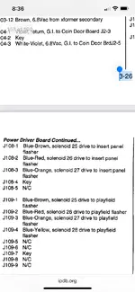
traced them back to the positive being a red with white strip going to PLFD J133 pin 5
right flasher is J109 pin 2 and left flasher is J109 pin 1
However, what im find confusing is the lower side the pins are right to left and the upper side of the board the pins are left to right ?
traced them back to the positive being a red with white strip going to PLFD J133 pin 5
right flasher is J109 pin 2 and left flasher is J109 pin 1
However, what im find confusing is the lower side the pins are right to left and the upper side of the board the pins are left to right ?
Asiapinball
Site Supporter
That's correct. If you look at a board with its locking mechanism downwards then pin 1 is on the left.
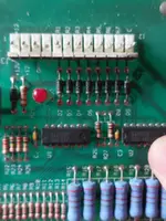
For the pins on the board they are always installed with the locking mechanism facing inwards so the pins along the bottom of the board are effectively installed upside down so pin 1 is on the right. Similarly connectors on left side of board have pin 1 at bottom and right side pin 1 at top.
The boards are usually marked on the screening where pin 1 is located. Eg on pic you can see pin 1 and pin 12 marked on the board screening.
Attachments
Asiapinball
Site Supporter
You can think of this as looking around the board in a clockwise direction pin 1 is always the first pin that you get to.
Maybe there are some exceptions so you should always check with what is printed on the board.
And the boards are usually printed as to what each pin does so you can also check that too. Keys are marked with an arrow.
Maybe there are some exceptions so you should always check with what is printed on the board.
And the boards are usually printed as to what each pin does so you can also check that too. Keys are marked with an arrow.
Asiapinball
Site Supporter
Flashers work the same way as coils. They should have voltage at the flasher bulb at all times so you can test that. They are in a state of readiness to be turned on by the switching transistors.
I have found that if you have power at lamps common issue with flashers particularly with #89 lamps is that there is a corrossion issue with the socket or bulb itself.
Otherwise there may be faults in switching transistors.
There is lots already out on internet already on testing solenoids and flashers.
Asiapinball
Site Supporter
All sorted. There actually wasn't anything wrong with them. I think the left lamp holder was not playing ball
Once I got my head around the system , lights being operated as electro magnets and this negative switching I checked through the test function and all fine
What's the deal with switching the negative? why not the positive like all electric circuits are ?
Once I got my head around the system , lights being operated as electro magnets and this negative switching I checked through the test function and all fine
What's the deal with switching the negative? why not the positive like all electric circuits are ?
Because it is easier to test the wiring with a voltmeter only and you don’t have to use the right power supply for direct coil/flasher testing, grounded wire works. A short will also throw the associated fuse immediately and not after switch activation, which protects the transistors to a degree.