What's new
Pinball info

Register a free account today to become a member! Once signed in, you'll be able to participate on this site by adding your own topics and posts, as well as connect with other members through your own private inbox!

The ongoing saga of the Roadshow mod

HomerRamone

Site Supporter
Joined
Mar 20, 2013
Messages
1,223
Location
Newcastle
Alias
HomerRamone
Thought I would start up another thread about it - since recent comments are not strictly relating to wanting a mod. (And also because some might not care about the trials and tribulations of me haggling with it and just want the mod !)

I revisited the mod again at the weekend. And I sorta made progress. I seem to have it working again (though not on the proto board I created)

However, irritatingly I dabbled with it last night, my plan was check it works with both of the ESP 32 deelys I have and once im happy with that, create another protoype board one step at a time - starting with making it just work when plugged into the board. Alas all was not well - and nothing has actually changed in the code that drives it :(
Last night it was behaving like this:

I have noticed that whilst the panels are meant to be 5v they dont behave at all when I set the PSU to 5v:

Looking at the reviews of the panels on amazon there are mixed ones. Several folks saying they are just not reliable and easy to kill. (Maybe this is just wishful thinking :D)
 
All meant to be 5v according to the amazon blurb. They really dont behave at all when I set to 5v.
 
what’s the spec of those panels. and what library are you using to drive them. ?

Also the quality of you connector cables can be crucial.
 
Lib was Fast LED IIRC.
Cables are just dupont cables. I seem to have amassed a collection of them with the various arudino/esp bits and bobs I have bought.

Pretty sure nothing has changed since I wrote the mod originally. I just parked it and forgot about it. When I revived it it was working... now last few times i've tried to use it its intermittent at best.
 
Data, CS and CLK

Actually the Library is Parola, but I think it builds on Fast LED
 
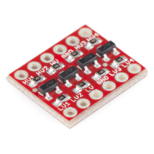
I think you may need to logic level convert your 3.3v ESP32 data signal if those LED panels are 5v.


Or, if you don't want to order the board, the schematics for it are available also.
 
The PSU has a setting to let me switch the voltage.

3,4 and 5.
The ESP is powered by the USB on the computer - its only the LED panels that need the power (AFAIK)
(Obviously the ESP will need power if it wasnt connected to my laptop)

Or am I missing what you are saying :)
 
Yeah it's not the power to the panels, it's the data line from the ESP32. Even if you're powering from 5v USB your ESP with be regulating that down to 3.3v and all the gpio will be that level too. Some LED devices can work fine powered from 5v and being driven by 3.3v, but with others the result will be unpredictable like what you're seeing. I'm almost certain that's the issue.
 
Will give it a shot.

The next obvious question though is why it was working just fine several months ago.

I did cross my mind I could use a couple a different panel. (I also thought of the ones @AlanJ has been using for his displays). But most of the panels I see are not quite as neat and have a move visible PCB attached. (Though I could print a plastic housing for it of course :) )
 
The last video in the original post - thats what happens if I connect 5v to the panel. So is that having an effect on the ESP then maybe ?
 
Will give it a shot.

The next obvious question though is why it was working just fine several months ago.

I did cross my mind I could use a couple a different panel. (I also thought of the ones @AlanJ has been using for his displays). But most of the panels I see are not quite as neat and have a move visible PCB attached. (Though I could print a plastic housing for it of course :) )

Oh sorry, that you'd switched out an arduino for an esp32? Or was it already working on a different esp?
 
Well it was working on a different ESP.
The original one was a V3 I believe and the latest ones I got were V4.
But been trying it with both of them and getting similar intermittent results
 
Okay that's a bit different then. Sounds like either you have a loose jumper cable in your bread board (super common) or like you thought, the panels are flakey, although weird that they decide to crack up when you changed the board over.

To test the breadboard connections, give em a wiggle at the connection points while your code is running. This is the main reason I stopped breadboarding actually.

For the led panels, i would order some more of a different make, even if they're unsuitable for prod, just to confirm if that's where the problem is.
 
Last edited:
Okay that's a bit different then. Sounds like either you have a loose jumper cable in your bread board (super common) or like you thought, the panels are flakey, although weird that they decide to crack up when you changed the board over.
To test the breadboard connections, give em a wiggle at the connection points while your code is running. This is the main reason I stopped breadboarding actually.
Its not a breadboard - its a sort of breakout board. Got 2 rows for the ESP to go into and screw terminals for the wires. I dislike breadboards too - hence the board. (Courtesy of @AlanJ IIRC)

For the led panels, i would order some more of a different make, even if they're unsuitable for prod, just to confirm if that's where the problem is.
Yeah I was thinking on rummaging in my various ardunio bits and bobs see if I had one I could try. Course anything that isn't an LED panel will require me to actually implement the animations - these are part of the library I was using. I originally used the lib because the first one I tried was really slow - found a faster one that also did some animations which was a bonus. Course ill take having to write some animations over the frustration of it just deciding not to work any day !
Most of the panels I found looking on the internets are serial - not sure how fast you will be able to update those. Especially if they are actual pixel based displays rather than just an 8x16 matrix of LEDs. Depends on the display format I suppose.
 
Data, CS and CLK

Actually the Library is Parola, but I think it builds on Fast LED
parola library has given me same issues with red led 8x8 matrix displays. the length and quality of the cables from the esp32 to the device seemed to be the major issue. i even had to wrap them in silver foil on one project try shorter and different wires
 
i’m pretty sure it’s a 5v board so only just gets enough juice out of a 3.3v processor to switch high. this is why spot on wiring needed. go for the level shifters up to 5v
 
i’m pretty sure it’s a 5v board so only just gets enough juice out of a 3.3v processor to switch high. this is why spot on wiring needed. go for the level shifters up to 5v

Cheap and easy


I usually just rebuild these circuits into my main design, they're pretty simple, just a tranny and two resistors. Send me a PM if you need a steer.
 
I was replying as you posted that. 😁
So tldr is get one of the boards suggested.
That goes in line from the esp to the Cs, clk and data on the matrix?
(curious as to how it ever worked cos it seemed to be rickety boo 4 or so months ago)
 
Yep all three lines should be level shifted. It will also require HV (high voltage, 5v) LV (low voltage, 3.3v) and GND.

Hard to say really what was the catalyst, but I can say I've had experiences very similar to this, but with led strips. All seems fine, then one minute, rainbow chaos.

Which would be a great name for a gay metal band now I think of it.
 
5v and 3.3. That's greed (but I can see how it works knowing that).
This is going to make it more fiddly to drive from the pin wiring then I expect?
 
Only in the initial wiring (and a slightly more complex board design in production). Is that what you mean? Code will be the same.

The other option (especially if you don't need the WiFi capability) is to switch out the ESP for a 5v controller, like an arduino nano.
 
Only in the initial wiring (and a slightly more complex board design in production). Is that what you mean? Code will be the same.

The other option (especially if you don't need the WiFi capability) is to switch out the ESP for a 5v controller, like an arduino nano.
Aha - I have a nano (well a couple in fact) which means I can try that out farily easily. Or I could except they wont fit in the terminal adapter deely. Doh.
But dont especially need wifi or anything so the only complication there I guess is the opto couplers need 3.3v IIRC. which means I will need something in the circuit to deal with that ?
 
They won't be 3.3v specific, and I'm guessing you were only doing that so the logic level being driven by them would be suitable for the ESP. Just run 5v to the source instead.
 
Tried with a nano last night.
Just got no meaningful display at all.
I might try connecting the earth from the psu and the nano together see if that helps. This feels like I'm clutching at straws though.

I guess if that doesn't help will maybe try using fast led instead see if I can at least coax some expected results from it.
Pesky panels.
 
Back
Top Bottom