What's new
Pinball info

Register a free account today to become a member! Once signed in, you'll be able to participate on this site by adding your own topics and posts, as well as connect with other members through your own private inbox!

testing lamp driver board transistors with a multimeter woes

stevebm1

Registered
Joined
May 26, 2014
Messages
1,622
Location
uk
I used to have an old multimeter that I bought at a boot sale years ago,that worked well when testing transistors on bally lamp and aux lamp driver boards.I lent it to my brother-in-law and he lost it,so he bought me a replacement,but it's one of those crappy yellow ones that cost about 3 quid on ebay,and this test will not work,despite being set on diode mode(I even tried it with brand new scr's still no joy.


MCR106-1 Lamp Driver SCR test:

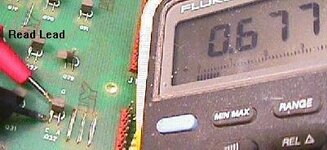
  • Put the black lead of your meter on the outside "cathode" leg (labeled "C") of the SCR.
  • Put the red lead of your meter on the outside "gate" leg (labeled "G") of the SCR. Your meter should read .4 to .6 volts.
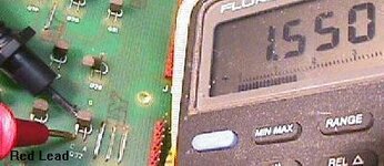
  • Swap the meter leads. Now the meter should read 1.4 to 1.6 volts.
If your meter reads anything outside the values above, replace that MCR106-1.

can anyone reccommend a cheapish multimeter that will perform the above test?
 
yeah maplins might be worth a look I suppose,didn't realise they let you test them first before you buy them
 
ok went into maplins today with a bally lamp driver board in hand + a print out of what is supposed to happen showing pictures of the fluke 83:

techniek.flipperwinkel.nl_ballyss_rep_testlmp1.jpg
techniek.flipperwinkel.nl_ballyss_rep_testlmp2.jpg

tried about six different meters but none of them would perform this test,the tech guy was as stumped as me,is it an error on the original webpage,or will it only work with an expensive fluke meter?
 
Last edited:
Well i think that article is perhaps wrong!
The 'C' to 'G' is just like a normal diode test. So the top pictures reading is correct, the lower picture should be reading 'OL'
is that what the meters you tried showed?
Bob
 
no nothing at all if you put the black on the G and red on the C the displays just showed a "1",the meters we tried were from 7.99 up to 60 quid,none of them worked
 
well thats correct and is indicating a revered bias junction thats OK
go back to Maplins and pick a meter you fancy, just make sure it has this diode check function and audible continuity
bob
 
sorry I didn't explain fully they were reading"1" as soon as they were switched on in diode mode without the leads even touching anything,touching the probes to the transistor like in the second picture made no difference they still all displayed a "1" on the screen
 
This is weird. I have a £20ish Maplins DMM and have used these same photos (from Clays) many times with it in diode mode to test 2N5060 lamp driver SCRs on my GOLD BALL and get the similar forward voltage drops shown.
 
Yeah, nothing wrong with the article. Fairly standard test although you might get different results with different types of transistors on different boards.
 
This is weird. I have a £20ish Maplins DMM and have used these same photos (from Clays) many times with it in diode mode to test 2N5060 lamp driver SCRs on my GOLD BALL and get the similar forward voltage drops shown.

do you have a photo or model number of the meter you have please
 
do you have a photo or model number of the meter you have please
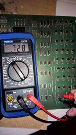
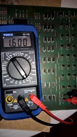
Better than that, being Sunday and pinball day I just ran & photo'd a test for you! A couple of things I spotted, the DMM reads '1' open circuit until you connect it across the component so that sounds ok, also if there's the slightest tarnish on the component leg (which there usually is) it won't make a reading so scratch it up a bit. This DMM does everything I need for pinball but I'd pay a little extra for one with auto shut off as I keep leaving it on.

WP_20161016_10_57_59_Pro.jpg WP_20161016_10_58_23_Pro.jpg
 
you sir are a star,I shall try and track down that model number multimeter then,it proves clays article is correct!
 
I'm glad you found the photos useful. My Maplins DMM appears to be obsolete but its nothing special and any should measure this on diode test I'd have thought. What I have noticed is that if I measure an SCR out of circuit ie a new one I get the same readings as you, approx 0.7 V Gate to Cathode and 1 (open circuit) Cathode to Gate.

Hopefully the more electronic minded guys on here can explain the difference and help you sort this.
 
Aston, I think you hit the nail on the head when you said to clean the transistor legs before measuring... :thumbs:
 
Back
Top Bottom