What's new
Pinball info

Register a free account today to become a member! Once signed in, you'll be able to participate on this site by adding your own topics and posts, as well as connect with other members through your own private inbox!

Terminator 2 flipper problem

Alstal

Registered
Joined
Oct 19, 2024
Messages
16
Location
Wicklow
Hey Everyone,

This is my fist time posting, I've been looking for solutions everywhere which brought me to your forums, I'm stumped.

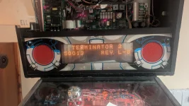
I bought a T2 pin way back in 2008, after a few months of playing the right flipper started to work intermittently and eventually stop working all together. The left one followed a few weeks later. At the time I had no idea what as I've no experience with electrics so I just tried to follow wires and check the fuses. But everything seemed fine.

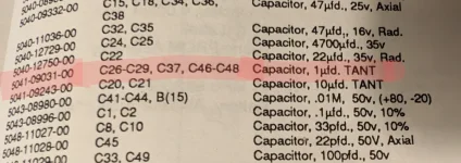
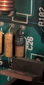
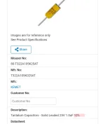
I had to move away for work so the game was put in storage. Finally moved home and built a house and have moved it into the future games room. Quick clean and check and it's powered on. Sound board blew a capacitor so it's disconnected till I fix it.

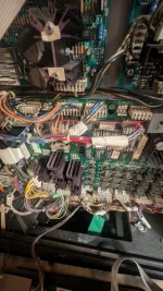
I've tested both flippers leaf switches, good continuity to and from the flipper control and power supply wires on the board. The solenoid flippers both work when I grounded manually, I'm sure that's a no no but I know they're working.

I have a little more understanding of electrics now but I'd still be a novice at best.

Any help would be much appreciated, it's a shame to have it stored for so long as it's been.

Thanks guys,
Alan
 

Attachments

  • PXL_20241019_134257380_exported_6768.webp
    PXL_20241019_134257380_exported_6768.webp
    70.1 KB · Views: 6
Was it stored with the batteries in place? Perhaps check for board damage caused by leaking batteries.

You've checked the switches which is good.

Are there any errors on boot up/test mode?

Do the rest of the solenoids in the same column/row as your flippers work?
 
The one thing I probably did do right was change the AA batteries every few years and checked for damage. Flippers are at the top of the board on there own unless I'm missing something (image attached) only code when I turn it on is 50013 REV L-8 attached too
 

Attachments

  • PXL_20241020_181448789.webp
    PXL_20241020_181448789.webp
    126.8 KB · Views: 11
The one thing I probably did do right was change the AA batteries every few years and checked for damage. Flippers are at the top of the board on there own unless I'm missing something (image attached) only code when I turn it on is 50013 REV L-8 attached too
 

Attachments

  • PXL_20241020_181029879.NIGHT.webp
    PXL_20241020_181029879.NIGHT.webp
    117.1 KB · Views: 19
Good about the batteries.

The code you see is simply the version of the ROM. So that's fine. If the system detects an error, it will make a sound and flash "TEST REPORT" followed by what it is telling you to is wrong.

The fact that it isn't, is both good and bad. It's good because there are no obvious errors, but bad because whatever is wrong it's not detecting.

If a switch isn't activated in a certain amount of games (I think 30?) then you'll get a test report. So the flipper switch must be activating somehow.

This could be a simple case that the connectors or pins are bad. You may need soldering, but do some basic things first.

1. With the game off, use a thin piece of metal or plastic to just push those wires in the connectors just a tiny bit. This may be all it needs, and may be the reason why the flippers slowly died. They're not making connection anymore.

Do this for all related connectors (check manual for the rows and columns on the switch matrix).

From the manual, you want to look at J207 pin 1 and pin 2. These should be marked on each side 1 and 9.

As both flippers are bad it's possibly a column issue, so do this for connectors J209 pin 1 and J209 pin 2.

2. Go into test mode, go to switch edges, and test the start button and the right pop bumper. If these work, it probably not a row or column issue.

3. Get a soldering iron and take the boards off. Check the connector pins don't have any cracked solder or anything. If you can and know how, resolder these.

But really I'm interested in step 1 and 2 for now.
Sorry, I've been up at J110 and J109, pushed in J209 1+2 and J209 1+2. In test mode the start button and right pop jet are working, just did a full solenoid test and left lock and kickback aren't triggering. On switch edges test the following are closed:

Through center
Through right
Always closed
Gun loaded
Gun mark
Gun home
Drop target
 

Attachments

  • PXL_20241020_192446153.webp
    PXL_20241020_192446153.webp
    74.3 KB · Views: 0
Ok, next check J127-9 and J130-9.

Do you have a wire with crocodile clips? You could use this to jump the pinned connections to isolate the issue whether it's playfield or board.
 
J127-9 & J130-9 Checked, left lock and kickback not working. I have just noticed every time I turn it back on it says factory settings restored. Imagine the would have something to do with the batteries that it can't hold memory? There was never any corrosion on them but could there be damage on the back of the board where the holder joins?
 
Potentially, you'll probably have to pull the board and check. Check continuity on the traces. You should pull the power board too. You may just have a cold solder somewhere.

I take it under the playfield there was no loose wires etc? That's worth a check in case it's something obvious.
 
I had a set of crocodile clips for the multimeter but god knows where they are now in this place, I'll need to order some and get back to you. Had a good look under the play field when I first went at it again but everything seems solid.
 
Ok. Might be worth taking the boards off regardless and give them a once over and reflow solder where possible and then see what's still broken.

May be worth replacing a couple of transistors too (Q44 and Q70) just incase.

Could also be the traces between the fuses and the other components.
 
Thanks so much for all this, I'll get the boards off and have a good look before I order everything I need. I have a friend who's good with a soldering iron so I'll probably pass that pressure onto him while getting a few tips. I've only ever done it on machinery. And I'll replace Q44 and Q70 when I replace the capacitor on the audio board. I'll keep you posted and thank you again for your help
 
The solenoid flippers both work when I grounded manually, I'm sure that's a no no but I know they're working

Hello, Alan,

In fact, that isn't a proscribed method of checking a solenoid, provided you ground the 'tail' end of the winding, rather than the live one. And don't leave the circuit 'made'.

One thing you should bear in mind is that T2 is one of the final Williams games before their introduction of solid-state 'Fliptronic' switching of the flipper coils, i.e. using transistors. For this game, the method used for decades remained in place; the flipper current flows through the coil, the 'End of Stroke' switch mounted alongside, the button-operated switch and then a relay contact before reaching ground. So grounding the coil by-passes all that return side wiring and contacts. The flippers are really a section by themselves, and those contacts will never show up directly in any of the switch tests, so forget about a Test Report for now. Sorry, but I have to mention that 'As both flippers are bad it's possibly a column issue' is leading you off in a wrong direction, at least in regard to the flippers not operating. The switches 'Left Flipper' and 'Right Flipper' you're hoping to see on the display will only show if the flipper coils operate, they're incidental to the main flipper circuits.

During your efforts, was the flipper relay (mounted on the large Power/Driver board) 'On'? If not, the flippers wouldn't operate, it's how the machine shuts off the flippers in Game Over and when tilted. The relay should snap On with a click when a game is started or when going into diagnostics. As with any solenoid, the relay itself can be operated by jumpering its winding to ground - one way to do so is to find its protective diode alongside* and jumper the Plain end of that. It should switch on the relay, completing the flipper return circuits. If the relay does switch on, then since you've shown the flippers themselves do work the problem seems to be in the switching/return side, such as burnt contacts, or poor connections where the wiring reaches the Power/Driver board, in that top left area. With the machine switched off, try checking continuity from the coil through to the board, then out to the button, the button switch itself, then back to the board, i.e. with a button pressed, there should be continuity from the tail-end of that sides' coil to the relay, or the vacant locations W 4 or 5 on the board, as in the footnote.

You mentioned, though, that one side became intermittent and then died, followed later by the other. That sounds like more like bad contact developing somewhere. The likeliest places are end of stroke and button switches.

The recurrence of Factory Settings Restored suggests that the AA cells have died, or the toy-like holder is broken. In that situation, the Test Report produced will be 'Time And Date Not Set'.

* from a pdf of the schematics, the diode is to to the left of the relay, it looks like 'D 39'. I'm also reminded that Williams provided a fall-back for relay failure; the outlines for 'W 4' and 'W 5' allow wire jumpers to be installed which by-pass the relay, so that the flippers should be 'enabled' at all times. Not a long-term solution, especially in a boozer or arcade, but an emergency measure.
 
Last edited:
Thanks so much for all that, I'll work my why through what I can. The relay does not click when starting a game or when in diagnostic mode. As discussed with Dinsdale I'll remove the board anyway to have a good look at the back. As for the fallback W4 and W5, the machine is personal use only so that option would work if all else fails and I'll make a note of it in my manual. Please see two photos attached to confirm
 

Attachments

  • 1729527691333.webp
    1729527691333.webp
    140.7 KB · Views: 29
  • 1729527623255.webp
    1729527623255.webp
    100.1 KB · Views: 28
Thanks for your approval,

The first picture shows the diode connected across the electrical winding of the relay, but please don't ground that end of it, use the other, unbanded end. The banded end (its 'cathode') is connected to the voltage supply for the relay, so grounding it would blow that. I don't recall just now if it's solenoid voltage or logic voltage, but it won't like that. The relay is (or should be) controlled by a line from the Cpu board, using the neighbouring transistor, Q 99. This line is routed through the ribbon cable between the two boards. With this age of machine, which tbf must be beyond their intended lifespan, failing ribbon cables aren't unknown. See the final paragraph, below

With the second picture, the jumper locations are indicated by white lines; linking W 4 and the vacant hole below will by-pass one side's relay contacts, intuitively I'd expect for the left, and similarly W 5 and its partner will by-pass the other.

Just to mention, those tiny chips (one of them in a socket) peeping into one of the pictures produce the indications for 'switches' Left Flipper and Right Flipper, but have no real effect on the flippers themselves.

I thought later on about grounding the flipper coils; depending on the procedure, it could tell us about the End-of-Stroke switches;

  • each flipper coil has three terminals, as it has two separate windings. Both windings begin at the Live side of the coil, an outer terminal with the banded end of a diode (diodes fitted to coils always have the banded end at the live terminal). Williams used wiring with a Yellow trace for connecting this, Blue with yellow on one side and Grey with yellow the other. Other than seeing the connections are good, leave these well alone
  • the Power winding of the coil emerges at the centre terminal - grounding this operates only the winding, without even involving the Eos switch, so only do this momentarily
  • the tail end of the coil (and the low-current Hold winding), is at the other side, with the plain end of a diode. Grounding this operates the entire flipper coil, but if the EoS is bad it'll be trying to operate without the power winding, and be pretty weak, if it moves at all
  • So if the flipper worked when grounding the centre terminal, but not the tail end terminal, the EoS would be open-circuit
If it helps, the wires from the tail end of each coil end up grounded in any case, if the buttons are pressed and the relay is On, so you could connect to ground at any point in the return circuit, to narrow down any possible break, e.g at the pins of driver board connectors (though not those feeding power to the coils), or the button switch. There should be a diagram of flipper wiring in the manual, and details of wires in each board connector. Pages 3-2 and 3-8

I see there are also two other solenoids not working; again the grounding method would show if the coils themselves are okay. Take care there, though. Williams had stopped placing diodes on coils (other than flippers) by then, so check which is the return wire. Usually the thinner wire, and a unique colour combination, rather than shared power supply wires. I wouldn't rush into replacing transistors as a first approach. A solenoid return can be checked by grounding the metal tab of the transistor; that terminal is connected to the tail end of the coil, so if the coil operates the return path is alright. It says nothing about the transistor itself, though.

There may be a clue there, actually, in which solenoids they are; the kickback is No. 8, the left side eject is No.16. Being separated by 8 suggests a problem with the cpu 'addressing' the solenoids, and has been mentioned by chaps more acquainted with the computer side. As I recall it's attributable to the ribbon cable, affecting comms between the two boards. See the topic 'Outhole solenoid dead on bsd', from December '21; bsd denotes the slightly later game Bram Stoker's Dracula
 
Last edited:
I unplugged every connector again and also the ribbons on all boards. Pushed in and wiggled every single wire, fuses out and in, Clipped it all back together and the great news is for the first time in over 10 years she's working again. Even the lock and kicker are working. Just the capacitor on the sound board to fix hopefully and it should be in great shape. I can't thank you enough for your incredible patience and all your help.
 

Attachments

I unplugged every connector again and also the ribbons on all boards. Pushed in and wiggled every single wire, fuses out and in, Clipped it all back together and the great news is for the first time in over 10 years she's working again. Even the lock and kicker are working. Just the capacitor on the sound board to fix hopefully and it should be in great shape. I can't thank you enough for your incredible patience and all your help.
Date/Time and free play settings are saving too 🥹
 
"For the first time in over 10 years, she's working again" - Arnie did say he'd be back..

Just out of curiosity, now, I see the software is edition L-8. I can't recall what the ones at work had, but I've wondered sometimes if a display text error was ever corrected. The High Score table is announced as 'Top Marksmen', but a player invited to enter initials is told 'You Are A Top Marksmen'.
 
Last edited:
"For the first time in over 10 years, she's working again" - Arnie did say he'd be back..

Just out of curiosity, now, I see the software is edition L-8. I can't recall what the ones at work had, but I've wondered sometimes if a display text error was ever corrected. The High Score table is announced as 'Top Marksmen', but a player invited to enter initials is told 'You Are A Top Marksmen'.
Yes, this and many other issues were fixed with L8.4 which is fan custom code which fixed many bugs. It is fantastic.
 
Thanks, it was just a niggle. There were some corrections made with other games, such as Popeye (correcting 'Tripple') or Black Rose ('Richochet'), but I don't suppose those were done specially.
 
May as well ask since I have your attention 😅

The burnt out capacitor on C26 is unreadable but I can make out a +3. but C37 has +1u0k +avx written on it and the manual gives it as 1µfd. TANT

When I go looking for a replacement it gives me 25v 10% or 50v 20%
 

Attachments

  • PXL_20241024_165217491~2.webp
    PXL_20241024_165217491~2.webp
    69.9 KB · Views: 10
  • PXL_20241024_170427542.PORTRAIT.ORIGINAL~2.webp
    PXL_20241024_170427542.PORTRAIT.ORIGINAL~2.webp
    36.3 KB · Views: 10
May as well ask since I have your attention 😅

The burnt out capacitor on C26 is unreadable but I can make out a +3. but C37 has +1u0k +avx written on it and the manual gives it as 1µfd. TANT

When I go looking for a replacement it gives me 25v 10% or 50v 20%
Ahh yes.. they are really starting to do that (plus they go off like a firework and scare the bejesus outta you!)...

C26-C29,C37,C46-C488105M=1uF Capacitor (25V,20%,Tantalum/Radial)

From Victor's repro wpc89 board BOM.

Available from Mouser :

If it's just the one or two you are after I'll take a look and see if i have any - i can then put one in on my next order (later in the week)...
 
Also it is worth saying on this game it does not use fliptronic flippers.

I would recommend fitting new EOS switches on the coils and new cabinet switches as well. You can clean them using cardboard but I would advise replacing.

High current is passed thru the EOS and cabinet switches.
 
Thanks for that, just double checking, the item you recommended is 25v,10% on the website. Is that correct?
Thats the one i have physically used when i have built repro sound boards, yes. Victors boards are for the most part 1:1 with the originals.

The 10% refers to tolerance - 10% is better than 20%...

Those tants are the ones that reguarly go pop nowadays - caused either by old age, or by other components going out of tolerance and then taking them out!


When these things fail, they often fail as a dead short. If your power supply does not detect this short and somehow keeps the power good signal high (it's 5v active high) and if it can deliver enough current these shorted tants will literally go kaboom exactly like in this video, which is what happened to him (only inside the case).. He did something I really wouldn't do though, bridging two power supplies when there's obviously something shorted out.. There's always a reason a SMPS won't start. It's always better to do some probing to find the cause but instead he decided to just blow it up, which also works I guess ;-) I did like the fireworks, but it's not recommended as there's a always risk you might cause more damage to your equipment..
 
Thank you Paul, I've ordered a few in anticipation of the next fireworks display!! Is there any difference between axial and radial capacitors other than shape? I can find radial capacitors locally here but assume there's a catch. Like the leads would be too short for a replacement.
 
yes, if leads are too short, you can cut the old cap off leaving the old leads and just solder onto them. You can also mount the axial cap vertically if there is room for it and spread each lead out. Or third option is to extend with a new piece of wire.
 
Thank you Paul, I've ordered a few in anticipation of the next fireworks display!! Is there any difference between axial and radial capacitors other than shape? I can find radial capacitors locally here but assume there's a catch. Like the leads would be too short for a replacement.
There shouldnt be a difference in the part itself operation-wise... the legs should be long enough, you just might have to be inventive with mounting it! It's pretty tight in there!
 
Alan,

With capacitors generally, the voltage stated is what the component can withstand, so a higher voltage is alright; over-specced, but okay. As Paul mentioned, the percentage is the difference from the marked capacitance (1 micro-farad in this case) that the component may actually have. It's similar to one of the striped bands on resistors, (Gold, Silver, etc) to denote the possible variation.
 
Back
Top Bottom