What's new

TAF suddenly won't boot

Durzel

Registered
Joined
Oct 1, 2017
Messages
2,041
Location
Bath, UK
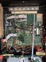
Booted Addams a few minutes ago, plunged a ball and the DMD froze and everything stopped working. GI stayed on but that's it.

Now when I power it on I get GI but no DMD output.

Opened backbox and no LEDs on the CPU board are lit. Some on the power driver board are, but solidly on instead of blinking like normal.

Don't really know where to start looking so any tips gratefully received.

Cheers.
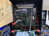
48BDA955-5C6F-4EFB-8543-9A6B036EC1AE.jpeg
 
Not yet. Are there any obvious ones that would stop CPU booting?

EDIT: Just checked them with power off. Didn't find that had blown. Do I need to pull each one to test?
 
Last edited:
From the looks of the driver board the following LEDs are not lit:

LED2
LED3
LED4 +5V

LED1 +12V, LED5 +20V, LED6 +18V and LED7 are lit.

I get nothing (well maybe 1V) at TP2 with a multimeter.
 
Last edited:
Yes. You need to pull the fuses to check properly.

You have no 5v hence the cpu won’t boot.

There’s a previous repair on the board. New capacity next to the heat sink. So maybe the 5v bridge has also been changed. If not done well then there may be poor joints on the bridge on the top side or the capacitor may be poorly connected to the bridge.

Check fuses first.

Only way to diagnose is to get the meter on it and see what is happening. With power on measure dc AND ac voltage at the 5v test point.

If absent then trace lack of continuity. Of present but with AC on the 5v then there is a capacitor problem.
 
Ok I pulled the 4 fuses on the right and tested them all, and all were fine. Will pull the rest tomorrow when I have more time, running out of light now.

Not sure how to test AC voltage with multimeter?

TP2 is definitely 0V though (not ~1V as previously thought)
 
Old DC?

I'm checking TP2, which reads 0V. F113 tests fine.

Have not tried testing connectors etc yet as don't know what to test or how to test AC.
 
Ac volts is the squiggle on your meter.
Dc is the flat line with dashes underneath.
Ac bolts you measure across the two cables of that line.
 
Hate to hammer on the same point you've answered already, but how are you checking the fuses with the multimeter?

Do a resistance check on each fuse and confirm very low resistance - partially-blown slow-blow fuses may initially buzz with continuity/diode checker modes on multimeters at first.
 
I was testing resistance with the meter, not tried continuity. All read a nominal amount.

I have not pulled all of the fuses yet but I have tested them all in place and they are all the same.

In terms of testing the TPs with DC, I was putting the black lead under the backbox braid. I don't know how to properly test AC and unfortunately "measure across the two cables of that line" might as well be Chinese. But thanks anyway Polbug 🙂

It sounds like I'm going to have to pull the board and send it off, unless there is anyone in the Bath/Bristol area who can help diagnose (will pay obviously)
 
So for dc volts you go witg black lead on test point gnd, red lead on 5v, then 12v test points
 
Old DC?

I'm checking TP2, which reads 0V. F113 tests fine.

Have not tried testing connectors etc yet as don't know what to test or how to test AC.

Meant 12volt odd, meaning roughly 12v dc
 
Last edited:
So for dc volts you go witg black lead on test point gnd, red lead on 5v, then 12v test points
Is any ground valid? Like a braid etc?

The unregulated 12v was about 15v from memory, 12v was 11.90v. Others were within spec as far as I could see. Only 5v was dead - ~0.01v on multimeter.
 
Forget the AC volts. If you have zero volts DC then there’s probably a break somewhere in continuity. Look closely at the solder joints on BR2 on the top side of the board.

Just for info. If the capacitor is badly connected then what you’ll get is a 5V that is somewhere near 5v dc , but if you change your meter scale to AC and measure at the same points, you will see AC volts on top of that. So if you were to put an oscilloscope on it you see a wave with say 2volts AC offset from ground by 4Volts, which gives an oscillating voltage ranging from 3v to 6v , which averages to 5v which is whAt your dc meter will read.
( these values are just to help explain, not what you’ll actually see )
 
Thanks again.

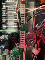
I just touched J101 with my finger while the machine was on and heard a pop (not loud), then it sprung to life. Checked TP2 and it read 4.97v.

I removed the connector and reattached it and powered off the machine and back on again and it worked.

I did trolley it back to its normal place and it stopped working again, so I again pulled off J101, pushed the wires a bit and plugged it back in, and now it's powered off and on fine 3 times in a row. I played a full game without it going wrong.

Does this mean my connector or the header is flakey? Or both? Or is that just pinball?

7A63DFCD-ED2D-46BA-A002-32AD0008FE86.jpeg

F16EBB70-827A-4AFF-A805-8719955DA926.jpeg
 
Try wiggling the wires one at a time to see if that effects it, might need punching back in connector or a cracked solder joint on pin.
Looks like you might have found your problem👍
 
The wires did look pretty well pushed in. I didn't try rubbing the header pins with iso or anything like that to make sure there is a good connection. I assume if there is a cracked solder joint on one of the pins that it's a board out job?

When it started working everything worked as normal and the 5v LED lit up along with the other two on the driver board that weren't illuminated, so it would seem on the face of it that the connector is the root cause of the problem.
 
Clean pins up like you say first but just disconnecting and reconnecting plug can be enough sometimes.
Yeah board will need to come out, pita but pretty straight forward. Label connectors if you want.
Resoldering pins is very easy.
 
Yeah, loads of connectors.. I was pretty intimidated at the thought of having to take it out :(
 
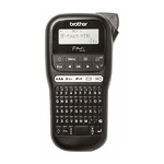
They are probably polarised to prevent mistakes but if you're worried why not label them - I recently bought one of these and anything that doesn't (or does) move gets labelled!
1564649117229.png
 
Yup I've got a Dymo labeller, if it plays up again I'll break it out and pull the board out. Will have to send it off for a cracked solder joint as I don't feel comfortable working on boards. Thanks :)
 
Will have to send it off for a cracked solder joint as I don't feel comfortable working on boards.
Do you solder at all? It really is straightforward reflowing dry joints.
 
I've soldered flippers but flippers are cheap and freely available. I'd be very wary of working on an unobtanium board. :(
 
Had a power issue with my TZ driver board a couple of months ago. Labelled all of the connectors before removing, very easy to take out and put back in, connectors tend to stay where you need them. Send it off to Phil at PH (by post), had it back working in less than a week.
 
Thanks all, and particularly Mfresh for your kind offer :) When I get some time I'll see about taking you up on that offer, much appreciated.
 
Back
Top Bottom