Pinball info
You are using an out of date browser. It may not display this or other websites correctly.
You should upgrade or use an alternative browser.
You should upgrade or use an alternative browser.
Complete STTNG - Flipper Rebuild, left, Right, Upper Right - First time using a soildering Iron! Subway clean and Ball Popper, Opto Rebuild and other things:)
- Thread starter cmrl9
- Start date
After some help from forum members, they kindly pointed out that I had wired the wires round the wrong way!
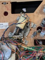
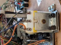
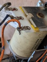
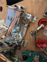
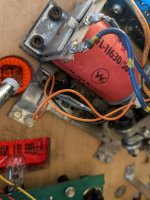
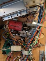
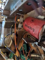
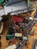
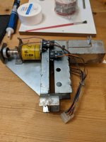
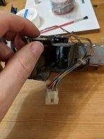
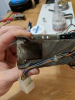
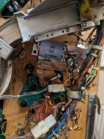
My smat idea of taking pictures only works if you know what a diode is and the banding direction on them. As the old flipper was flipped 180 degrees the grey and the orange wires where the wrong way round.
Desoldered and swaped them around to the correct way.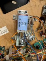
My smat idea of taking pictures only works if you know what a diode is and the banding direction on them. As the old flipper was flipped 180 degrees the grey and the orange wires where the wrong way round.
Desoldered and swaped them around to the correct way.

Feeling happier with my self that the non electrical cliffy protector was now fitted and working (well it doesnt technically do anything) went back on the help forum for some guidence with the left flipper hold problem.
Turn on the machine still the same old problem, back and forth in the help forum before I swapped the wires and after, was informed that it makes no difference which way round the wires go on the EPOS switch,.
Still a postiive I cn take from the time wasted is that the soldering is a lot better on the swap over!
Pondering whether to break the machine some more by changing the right flipper or leave alone!
Still a postiive I cn take from the time wasted is that the soldering is a lot better on the swap over!
Pondering whether to break the machine some more by changing the right flipper or leave alone!
If you're getting a fuse blowing on start-up every time after you've had a problem with the flipper diodes - there is a likelihood that the related transistor on the driver board was killed.
If you get the manual for the game (online or in print) you can find the related transistor for the left flipper, and with the machine *OFF* check the transistor with a multimeter for a dead short. Compare it to a transistor for a similar coil that you know works if you're not sure what you're looking for. Transistors don't always fail dead-short, and may present as a failure in other ways including inconsistent values with a multimeter (as testing them with a multimeter is really not even close to an ideal way to test them) - but in my experience, diode mishaps result in shorts in the driver transistor.
If the transistor tests bad you'll need to get the transistor replaced.
Hi,If you're getting a fuse blowing on start-up every time after you've had a problem with the flipper diodes - there is a likelihood that the related transistor on the driver board was killed.
If you get the manual for the game (online or in print) you can find the related transistor for the left flipper, and with the machine *OFF* check the transistor with a multimeter for a dead short. Compare it to a transistor for a similar coil that you know works if you're not sure what you're looking for. Transistors don't always fail dead-short, and may present as a failure in other ways including inconsistent values with a multimeter (as testing them with a multimeter is really not even close to an ideal way to test them) - but in my experience, diode mishaps result in shorts in the driver transistor.
If the transistor tests bad you'll need to get the transistor replaced.
The fuse only blew once, was F904 lower left flipper, when I turned it on to test my handywork and again when I thought it was a blown fuse.
After that I didn't turn the machine on until I had swapped the wires around. The fuse is no longer blowing.
Regarding the rest of the troubleshooting that probably above my skill set!
Nope I don't have a mulitmeter, I do hve one on back order from pinball Heaven, it was one of the few tools that hadn't yet been delivered. You would be correct I don't have a clue how to do a continuity test.Have you even got a multimeter and do you know how to continuity test?
Which fuses did you replace? the one one driver board or the one on the fliptroinic board?
Only one F904 lower left Flipper, twice, once just after fitting the flipper, second time thinking it was a blown fuse. Third time after I had fixed the wiring problem. Hasn't blown since the couple of times Ive had the machine on.
Its the bottom left on the flip tronics board.
I took the board out to see if there where any burns on the conenctors or underside, all looks clean, but I would'nt really now what I would be looking for except for burn marks!
biglouieuk
Site Supporter
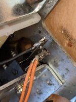
Because you swapped the diode tab from the back (coil stop) to the front (where the rod sticks out) you maybe confused yourself, with the way the wires go round. I did the EXACT same thing first time I did a flipper rebuild.I desoldered the wires, cut the bad ends and used Rosin Paste flux.
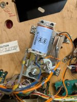
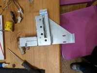
I then striped the wires and attempted to resolder them back onto the new pre-built flipper.View attachment 124408
I try and take a picture of it with the rod pointing upwards, to orientate myself. Your wires look good now (orange to the left as you look with the rod upwards), hence why it's not blowing the fuse? (this is a bit of the blind leading the blind here!)
So whats next? the yellow EOS wiring?
Last edited:
Only one F904 lower left Flipper, twice, once just after fitting the flipper, second time thinking it was a blown fuse. Third time after I had fixed the wiring problem. Hasn't blown since the couple of times Ive had the machine on.
If you've not got a meter to test the fuse then it is most likely blown and that is one of the reasons why the flipper is not working.
You need to replace the relevant transistor on the fliptronic board and check the resistance (you need a multimeter to do so) of the flipper coil to see if that need replacing as well. These need to be done together or one will continue to blow the other.

