What's new
Pinball info

Register a free account today to become a member! Once signed in, you'll be able to participate on this site by adding your own topics and posts, as well as connect with other members through your own private inbox!

Strange Science Power Transformer Voltages

Andy B

Site Supporter
1 10 Years
Joined
Oct 6, 2014
Messages
1,424
Location
Hull. England.
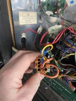
If anyone has a Strange Science would they mind uploading a photo of the connector, in the backbox, that supplies the voltage to the transformer (also in the backbox) from the on/off switch please - see my photo below.

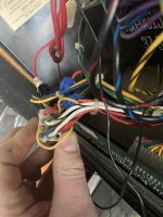
I have 240V coming in to that connector via blue and yellow wires from on/off switch as per wiring charts in manual but also on the "in" side of that connector I have a couple of orange wires that are acting as links to connect wires on the "out" transformer side. The in and out sides of the connector are aligned correctly as someone has marked each side with a felt tip.

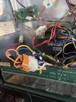
I have some totally weird/off voltages coming out from the transformer to the Power Supply Board (connector J5) and I can only think that one or more of these link wires has come out at some point and been put back in the wrong pin holes so the transformer is being supplied with incorrect voltages..

Thanks

Andy
 

Attachments

  • IMG_0897(1).JPEG
    IMG_0897(1).JPEG
    123.5 KB · Views: 15
  • IMG_0895(1).JPEG
    IMG_0895(1).JPEG
    96.1 KB · Views: 15
  • IMG_0896(1).JPEG
    IMG_0896(1).JPEG
    94.3 KB · Views: 16
Looks like you're correct and it's wired wrong according to the manual (one has to hope the manual is correct in this instance).

On the brown connector, top right corner pin should be Yellow (correct).
pin 2 underneath should connect to pin 8 (not pin 7)
pin 3 underneath should connect to pin 6 (not pin 8)
pin 4 vacant (correct)
pin 5 (middle top) should have Blue (instead of pin 6 having blue)
pin 6 feed from pin 3
pin 7 should connect to pin 10
pin 8 feed from pin 2
pin 9 (top left) vacant
pin 10 feed from pin 7
pin 11 & 12 vacant

Other side (clear connector) top left corner should be red (correct)
pin 2 underneath should be black (not white-black)
pin 3 should be orange-black (hard to tell in picture)
pin 4 white-black (not blue-black)
pin 5 (middle top) links to pins 6 and 7
pin 8 should be red-black
pin 9 (top right) should be red-yellow
pin 10 should be blue-black
pin 11 should be white

Good luck !

Thanks mate. What page of manual is that lot on? I have the manual but can't find anything covering wiring to transformer (other than blue and yellow wire carrying mains voltage)?

Cheers

Andy
 
Strange. Still not working. Looking at that connector on the brown side according to diagram it should have 3 link wires but the one I have in only has 2 link wires and yet the game was working before it was brought to me.

Anyone have a photo of the wired up connector they could post up please?
 
Last edited:
Sorry, just looked at the photos I took of mine when I had it, but no pics of that connector, sorry.

I'm wondering if this was the same machine I owned? That did have a loose wire in that same connector, so the game kept losing power.
 
Sorry, just looked at the photos I took of mine when I had it, but no pics of that connector, sorry.

I'm wondering if this was the same machine I owned? That did have a loose wire in that same connector, so the game kept losing power.
I think it may well have been. Did you sell it to Lee at Arcade Hub in Hull (it’s his machine I’m trying to fix)?

I know he had a power issue when he first got it and the advice was to check out loose wiring in that connector.

It stopped working a couple of month’s back and he’s brought it to mine so had the back box down and back up again when he dropped it off here so I was thinking wires from on/off switch may have been disconnected but 240v to that connector is good (and the Neon topper which taps off that connector briefly flashes when you switch it on (but does not stay on)) so has to be something with supply of voltages to transformer from that connector which is messing the voltages up that come out from the transformer (which are way off)
Neon transformer feeds are red and orange-black and supply 115v.

Just noticed the table a box - for link 220v only link 4 to 8 and 7 to 9 for 240v link 4 to 8 and 7 to 11. Confirms that only 2 links required unless using 115v or 120v.
 
Yes that is the one and the same then - it was sold to Lee as I recall can't remember if Martin took it in the end or not. I will check if I have any pictures of there, but don't think I will have. Has someone attempted any rewires since it left, as if not they are right.
 
Yes that is the one and the same then - it was sold to Lee as I recall can't remember if Martin took it in the end or not. I will check if I have any pictures of there, but don't think I will have. Has someone attempted any rewires since it left, as if not they are right
Yes that is the one and the same then - it was sold to Lee as I recall can't remember if Martin took it in the end or not. I will check if I have any pictures of there, but don't think I will have. Has someone attempted any rewires since it left, as if not they are right.

Yes, sounds like it. We haven't rewired it since he got it but there has been some "jiggling" about of those wires over time :-).
 
i’d just test continuity in and out for each wire in that connector. it will be only 1, i guess that’s not making contact.
 
ps took me ages to figure out why the neon was not working when i bought it. the wiring colours were not as per manual. i manually treated it and figured it out and hey presto the neon worked. so what i’m saying is, don’t trust the manual and machine agree
 
ps took me ages to figure out why the neon was not working when i bought it. the wiring colours were not as per manual. i manually treated it and figured it out and hey presto the neon worked. so what i’m saying is, don’t trust the manual and machine agree
Thanks for the tip. Bit worrying when you can't rely on the manual - especially when messing about with high voltage (there's a song in there somewhere...Danger, Danger...)
 
Reflowed solder joints on J5 and J6 on power supply board and all working now except displays - with no 190VDC at TP2. Diode at D10 is testing dead so fingers crossed it's just that.
 
Back
Top Bottom