What's new
Pinball info

Register a free account today to become a member! Once signed in, you'll be able to participate on this site by adding your own topics and posts, as well as connect with other members through your own private inbox!

Some GI out on Data East WWF

Dinsdale

Registered
Joined
Oct 19, 2022
Messages
391
Location
UK
Hi folks

Ok, I've got some GI out on my Data East. It's in the middle-ish of the playfield. All other GI is fine.

I've swapped bulbs too and they all work fine in other parts of the playfield.

I checked all fuses and they checked out good. Replaced a couple that weren't giving as strong a beep on the multimeter just to be on the safe side.

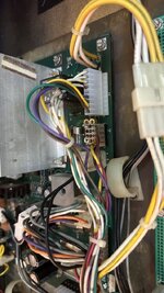
Connectors look good, although one looks brand new male and female so there may have been issues here in the past.

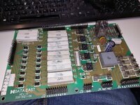
Have tried to read the manual and page 67 references the circuit and talks about 4M and F6... but I am not sure F6 is meant as a fuse in this context but also I'm not sure what it means exactly. I do think that all my troublesome lights are on the yellow and yellow-white circuit. Manual here: https://www.progettosnaps.net/manuals/pdf/wwfr_106.pdf

I put my multimeter to 200AC and placed in the pins on the PSB and didn't get anything but I may have done this incorrectly.

Could it be one that bulb holder is bad on that string?

Without taking the board off and reflowing solder joints, is there anything else I can check?
 
Fuses in question are F1 and F3 on the lower left board. Are the fuse holders ok, they tend to get brittle. Lamps are 6V AC so set your multimeter accordingly. Can’t be a single bulb as they are all connected in parallel, can be a disconnected wire. 4M F6 references the connectors and boards.
Trace back the cable from the GI string and measure across the respective plugs, again, should be 6V AC. Cables originate from PDB (upper left board, upper right corner) and the banded cable side is looped via the fuses on the PPB board (lower left). Page 63 shows the various boards with connectors and cable colours.
 
Last edited:
Fuses in question are F1 and F3 on the lower left board. Are the fuse holders ok, they tend to get brittle. Lamps are 6V AC so set your multimeter accordingly. Can’t be a single bulb as they are all connected in parallel, can be a disconnected wire. 4M F6 references the connectors and boards.
Trace back the cable from the GI string and measure across the respective plugs, again, should be 6V AC. Cables originate from PDB (upper left board, upper right corner) and the banded cable side is looped via the fuses on the PPB board (lower left). Page 63 shows the various boards with connectors and cable colours.
Thanks. I'll try that and get back to you.

There are some fuse holders that don't sen to belong to a board though. I don't know if this is a bodge job or supposed to be that way. I'll get pics tomorrow but they're in the very lower left.
 
Photos please. Are you talking about inline fuses in the wires?
 
These are normal, top one is 32V for coils, bottom 18V for lamps (NOT GI). I am always amazed how DE scrambled these pins together without a lot of rhyme and reason. Williams was head and shoulders above this and their solution wasn't the best. Shows how these boxes were created for a couple of year in the arcade and then to be dumped.
 
I think '4M' and 'F6' may refer to areas of a circuit board; D/E seem to follow video game practice and divide a board into sectors, like the index of an A-Z map refers to "------- St, 4A, (page) 77" f'r instance. I found this when Crewey asked about a D/E Cpu board.
 
Fuses in question are F1 and F3 on the lower left board. Are the fuse holders ok, they tend to get brittle. Lamps are 6V AC so set your multimeter accordingly. Can’t be a single bulb as they are all connected in parallel, can be a disconnected wire. 4M F6 references the connectors and boards.
Trace back the cable from the GI string and measure across the respective plugs, again, should be 6V AC. Cables originate from PDB (upper left board, upper right corner) and the banded cable side is looped via the fuses on the PPB board (lower left). Page 63 shows the various boards with connectors and cable colours.
Ok may some stupid questions.

1. Which setting?
IMG_9149.jpeg

2. When I power the game on, do I measure on the lugs of each bulb holder to make sure I get 6v? Does it matter which side I put black and red on?
 
V¬ 200 - the one to the right 2 positions, under the "HOLD" Button is your Lowest AC setting. it should measure 6V AC ok.

it doesn't matter which way round you have the red and black as you are measuring AC - Alternating Current. The current switches direction 50 times a second. Red and Black apply if you are measuring a DC (Direct Current) Voltage.

Yes measure across the lugs of a working bulb - you should see 6.3v or thereabouts, then try moving around to the unlit ones and you should find the break in the wiring. There are only 2 wires, one must be broken/dropped off somewhere.
 
Ok, I am getting between 4-7v on a working bulb. Nothing on a none working bulb BUT I am finding that it does make a difference on a working bulb if I swap round the red and black probes?! So now I'm even more confused.

I can't see any breaks but I'm going to keep looking.
 
Good news and bad news.

Good news it is fixed. Bad news is I have no idea how. All bulbs started working again.

There was a pinched wire that was on top of the playfield that was stuck in a bulb holder that didn't have a bulb in it, but I don't think it was that.

Weird. Going to be replacing these with LEDs soon anyway but for now we are looking good!

Thanks for the help, at least I had a refresher on the multimeter!
 
May well have been that - just work it out based on the color of the wire. Pinched wires sometimes "reform" but this is the insulation pulling the core together enough to make contact. That won't work forever. No bulb doesn't make a difference as they are all connected in parallel.
 
Wire was green and blue, but it is coupled with a yellow and white wire that's going up to a switch. Guess that's not the same circuit?

IMG_9151.jpeg
 
No, that shouldn't be related, especially if going to a switch. Must have wiggled something in the harness then, given the whole string was out this is probably between the playfield and backbox. The plugs love to burn up so can very well be that or failed solder on the PPB board. You could wiggle the connectors a bit to see if it fails again.
 
So far, so good. I'll keep an eye on it. I won't be playing it in anger for a while as I am waiting for replacement playfield parts anyway.

Thanks again!
 
This has went again. Same issue but I did hear a little pop. Checked all fuses and all test good (even out of machine to double check).

I was putting new comet flash lamps in though, so I've definitely did something. Been all over it with the multimeter and not getting any readings, so no idea where to start. Will keep looking.
 
Just bring your PPB Board over and we can fix it if needed. There isn't much on it to do with the GI - likely to be fuse clips and or connector pins. Just take a note first of which GI are problematic (green circuit or yellow circuit). But we will check out all circuits anyway.
 
It's unbelievably awkward and almost impossible to get my multimeter to touch the connector while having the playfield up as well. Backbox door being open won't allow playfield to go up.

But I did check all soldering on the effected lights and it looks good. One is directly behind a coil assembly though but it looks ok.

Driving me crazy. I'll just hope it'll come back on eventually.

But while I was down there I did fix a switch issue that seemed to be a misaligned pin on a z connector, multimeter helped confirm it was a physical issue rather than a continuity issue so that's a plus.
 
*** DIsclaimer: don't have a DE ***
Can't you take the connector of the PPB and drop it down into the cabinet? That should allow you to measure end to end.
 
*** DIsclaimer: don't have a DE ***
Can't you take the connector of the PPB and drop it down into the cabinet? That should allow you to measure end to end.
That's what I thought, but the wires are so tight and rather neat, I'd have to all kinds of connectors apart - and knowing my luck, I'd ******** something else up.

I am going to take my PBB off altogether though and @Asiapinball will take a look at that at least - hopefully the issue is there.

It's minor in the grand scheme of things but it's annoying the hell out of me.
 
Sorted it. Did continuity tests on entire string, all good.

Finally turned the connector round and it worked.

EDIT: I've now knocked out a row of columns. Unrelated after reversing my change. Laughing at how ridiculous this is getting.
 

Attachments

  • IMG_9234.jpeg
    IMG_9234.jpeg
    99.7 KB · Views: 10
Last edited:
Meaning you have a problem with the header most probably. It looks replaced, good chance the throughhole plating got damaged in the process and plugging in reverse tilts the pins enough to make contact. Lever the plastic off and check.
 
It's all good now. Was a loose connector for the lamp column, but reversing the initial change even has meant the GI has came back to life. It's a new connector so maybe it's just a bit stiff but sorted now.

Learned a lot here though, so not wasted.

I now have all switches, lamps, coils, flashers workings for the first time since owning the game.

Getting there!

Thanks again for all help.
 
Is the photo before or after you turned the connector around. If it is after then it looks like the connectors have been put in the housing in the opposite order to the correct order. There is a locking ledge on the connector housing which should be on the other side to what is in your pic and not visible if correctly installed.
 
Meaning you have a problem with the header most probably. It looks replaced, good chance the throughhole plating got damaged in the process and plugging in reverse tilts the pins enough to make contact. Lever the plastic off and check.
If it looks damaged just bring it next time you are over and i will reflow same as I did for the ppb board or should it be required do more extensive repairs if the through holes are damaged.
 
Connector can be reversed without affecting function which is what @Dinsdale has done here. This will put different stress on the pins and in his case get them to connect. Needs a reflow at least
 
Looking at manual solid wires should be at top on pins 1 to 4 and white and stripe wires should be lower pins 6 to 9. So I expect the pic is the before pic and not the after pic.

Agree @drhex the psu needs a reflow at least.
 
Back
Top Bottom