What's new
Pinball info

Register a free account today to become a member! Once signed in, you'll be able to participate on this site by adding your own topics and posts, as well as connect with other members through your own private inbox!

Shaker Motor in Elvis

Andy B

Site Supporter
Joined
Oct 6, 2014
Messages
1,375
Location
Hull. England.
15862890-9CE9-42DB-90D2-C9AFF55AB056.jpeg Anyone fitted one of Phil’s shaker motors in an Elvis and can send me photos please?

I thought I was a reasonably intelligent guy but clearly I’m not because I can’t for the life of me figure how the heck to wire it up!

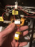
I have a red/white wire coming from back of cab, clearly labelled as being power for optional shaker motor but that wire continues on past the ‘intersection’ where the shaker motor is designed to hook up to terminates at coin door safety switch. There’s another couple of wires to a connector which is meant for the interface board which is not needed for Phil’s motor.

I can’t find the brown wire that’s supposed to be somewhere at back of cab that Phil told me to look for. The only brown wire I can find coming from back of cab is connected to a board on back of coin door.

Anyone help please - photo above.
 
Sold mine on eBay about 3 weeks after fitting it. Just saying.
 
Not working Phil. Any ideas please?

Cheers

Andy
 

Attachments

  • B02DB0D2-59C1-45D3-9DF9-8252D6790415.jpeg
    B02DB0D2-59C1-45D3-9DF9-8252D6790415.jpeg
    82.1 KB · Views: 14
No, doesn’t work in coil test. Doesn’t appear to be an option in the adjustments to switch it on or off Garry.

The wire color according to the diagnostics is supposed to be brown/yellow but the wire in the 7 pin connector is violet/yellow but the 7 pin connector is definitely labelled up as for the optional shaker motor
 
1) check the fuse on the motor
2) check the diode, the band should be on the end furthest from the fuse holder

I doubt it's either as all motors are run before sending.

can you check there's 12v at the 7 pin connector?

More likely it's where that 7 pin connects to which means tracing the violet wire and I bet it plugs into a connector in the loom at the back of the cab (where I normally plug the connector into).

I apologise for this Andy, the first few machines were all wired different. If we can't get it working I'll offer you a full refund.
 
No worries Phil, I know it’s not your fault.

Traced violet/yellow wire back, and you’re right, it connects via 24 pin molex connector to the brown and yellow wire that connects to pin 5 on J7 of i/o power board so is correctly connected to back.

Fuse and diode are both good.

Only getting between 10.5 and 11v at 7 pin though.
 
It'll work at that voltage
Can you then check at the end of the diode for the same voltage if none then its something between the 7 pin and the motor. If there is then it must be the signal side. Ground the centre tab on the correct transistor and see if anything happens
 
9.5v at diode.

Nothing happens when I ground transistor at Q4 but it tests good - has same readings as the other transistors which are all STP20N10L - 0.5v on top/left leg with black lead of DMM on tab.
 
ok, so there is power but no signal So we need to test continuity between the transistor and the 7 way connector next, then from the connector to the motor...
 
Just Taking Care of Business (but not in a flash).

Cheers Phil - will try the continuity tests when I get home tonight - thanks for sticking with me on this one!


Andy
 
Continuity was all good Phil. Trasnsistor to connector. Connector to motor.

Whilst I was testing continuity to motor and checking connections I wiggled something that looked Ike a copper leaf switch blade and it clicked - like the click you get when a relay pulls in.

After I’d done that, went in to diagnostics to test motor and it worked.

Booted up game as normal and it works a treat!

Really like the effect of the shaker on the game, particularly when ball is amongst bumpers.

Cheers Phil.

Good job that!

Andy
 
Back
Top Bottom