What's new
Pinball info

Register a free account today to become a member! Once signed in, you'll be able to participate on this site by adding your own topics and posts, as well as connect with other members through your own private inbox!

Robocop / Data East; Help please

Crewey

Site Supporter
Joined
Dec 19, 2021
Messages
1,352
Location
CH4
Hi All -

If someone could be so kind as to point me exactly where I need to check with my multi-meter please.

The coil under the centre pop bumper melted the sleeve earlier this week, both were in a very bad way so were binned and I ordered a like for like new one.
In the meantime I've also followed the wires, and checked every damn inch of the cabinet and backbox I found a couple of lose wires/resistor connections on the other two pop bumpers (soldered these) although these still work fine. No obvious signs of blown fuses or scorching anywhere.

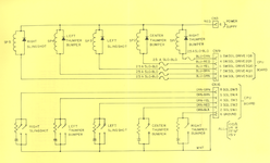
Fitted the new one this morning; it is not working at all. I have looked at the schematics and I'm in over my head, the schematic references where I 'think' I should be locating I can not see labelled on the board diagrams or on the boards themselves :hmm:

If someone could be so kind to explicitly spell out where I need to be checking? Thank you in advance wonderful people :thumbs:

Robocop Manual
 
Last edited:
Apologies if you have already done this but the first thing I would do is properly check the appropriate fuse for the pop bumpers. When you say no obvious sign of blown fuses - a blown fuse is not always obvious. You do need to pull it out and check it with a multimeter for continuity. But you also need to worry about why the previous one locked on till it melted as the new one will too if the same problem persists. Have you checked the bumper's switch to make sure it is not activating the bumper all the time? Then maybe the driver transistor?
 
Thanks mate, I've not tested anything with multimeter as I can't locate the schematic ref's to the board sadly

Donkey Brains I'm afraid 😐
 
with a fuse you pull it out and check it works with multimeter, no need for schematics but this should help:

Screenshot 2022-06-18 at 15.53.06.png
 
Q9 on the CPU board is the driver transistor by the looks of things. Maybe test that (you can Google how to do that)? It's a TIP122 but if it needs replacing then use a TIP102.
 
with a fuse you pull it out and check it works with multimeter, no need for schematics but this should help:

View attachment 173344
Fuse blown, incorrect one installed by the looks as not a slo-blo

Q9 on the CPU board is the driver transistor by the looks of things. Maybe test that (you can Google how to do that)? It's a TIP122 but if it needs replacing then use a TIP102.
Q9 reading same as the other transistors, seems ok thanks
 
When mine stopped working it was the transistor not connecting properly, somebody had done a bad repair and the common track they all connected to was iffy.
You will have to take the board out to have a look underneath though.
You need to make sure the switches do not stay closed on the solenoids and are adjusted properly as they are not computer controlled and will just lock on, think it was @myPinballs that mentioned this before.
What I found, the pin just leaning up against the link😂
1655641473951.jpeg
 
Last edited:
Holy Moly !
As there were 2 resistors and 1 wire that had disconnected between the 3 pop bumpers I'm really hoping this contributed to the blown fuse rather than anything else 😳
Checking the transistors over with the multimeter (frontside) they're not shorting , and provide sensible readings. But I will take a look at the back of the board soon.
 
I don’t think yours will be anything like mine though, it was a WTF moment but at least an easy cost free fix😂
 
I have checked, tip top shape the back of the board here .... phew
Got some SB fuses arriving tomorrow :thumbs:
 
When mine stopped working it was the transistor not connecting properly, somebody had done a bad repair and the common track they all connected to was iffy.
You will have to take the board out to have a look underneath though.
You need to make sure the switches do not stay closed on the solenoids and are adjusted properly as they are not computer controlled and will just lock on, think it was @myPinballs that mentioned this before.
What I found, the pin just leaning up against the link😂
View attachment 173467
Scheezus!!!
 
Would replace the transistor as well

The multimeter test is not 100% accurate.

Had an addams family with stuck on hold power this week. Tested the TIP and it was fine. Relaced it and it cured the issue. Tip102/122s can leak!
 
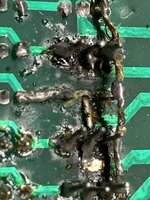
New fuses did nothing but blow. Received new transistors today, fitted what appeared to be correct at Q9 (trimmed legs @Jagspete before removing old one, however I still messed the vias up a bit think)
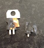
Turned on the game. Manually activated the centre pop bumper, the other 2 pop-bumpers reacted o_O uh-oh then immediately POP & smoke from the backbox the fuse is still intact and did not blow but the transistor is no more....
Very reluctant to even turn the game back on now, as I fear what else I could have royally effed up 😔

IMG_0411.JPGIMG_0414.JPG
 
Ohhh my lord ffs... just gone back to my original attempt at replacing the coil.
The diode is reading very little resistance compared with the other 2 coils, removed it and it does appear that the configuration is reverse to the others and I'd solder it the incorrect way around to being with.... god damn it

Read the label on the coil..... wait a minute... I didn't order Coil 26-1200 090-5044-0T from @pinballmania

Coil 23-800 090-5001-OT - Diode Fitted is on my invoice which matches the others for Robocop, my bad for not paying attention when I received the item 😭

So I've not just fitted a coil the wrong way around, I've also fitted the incorrect coil :eek:
No idea what way around to start piecing this together now.
 
No idea what way around to start piecing this together now.

Yes, you do and you've done it all already.

Start with replacing the transistor again (you can test using the multimeter) then the solenoid for the pop bumper making sure it's the correct coli and the right way round for connections this time (double and triple check). Finally replace the fuse as it could have welded itself. Leave the game switched off throughout until everything has been completed.
Thanks :thumbs:
Andy is sending me the correct coil replacement.
 
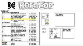
Troubleshooting the rest of the potential issues I've caused by being a muppet, I could see that F5 PSB had blow. Replaced, blown again. All other fuses appear ok.
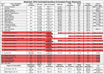
Going through the system tests; the red highlighted below no longer work.

switch.png
fuses.png
 
Been staring at the schematics and searching on pinside for similar issues, most threads there either abruptly end with no conclusion or the flippers are also not working in conjunction with the rest.

Is it a case of me having to pull the board and check every transistor and diode that’s relative to F5? To at least get back to where I was at the start of the day with just the centre pop bumper not working

Dude - we have all been here at one time or another . It might be time for your own sanity to get a man in 😁

A frustrating issue like this can end up making you hate a game. I talk from experience 🤦‍♀️
 
I hear ya @Sgt GrizZ if I hadn’t just used Jim’s services to sort PinBots music issues I’d be throwing cash at it to resolve this too.

I’ve got the time to test and diagnose as much as needed, it’s a frustrating and fairly blind task without direct guidance from the kind folks on here or pinside.
 
Diconnect all the drive connectors to the coils and flash lamps. Thats the two connectors below the bank of transistors, the connector for the special solenoids, and J9 and J2 on the PPB.

Replace the blown fuse. Switch on. You have no loads, so the fuse should be ok.

Now carefully offer up each disconnected connector to its plug. Start with the PPB connectors first. Don't push them on, but lightly make contact with the pins. If there is any short on that connector you will get a spark at the errant pin. Remove the connector as soon as it sparks to save he fuse. If no spark, this connector is ok to put back on. The sparking pin will identify which transistor/coil is at fault.
 
Morning Andy @pinballmania -

Thank you for this mate, I have attempted your suggestion and presumably have done it incorrectly.

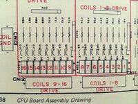
Firstly disconnected J2 & J9 on the PPB, and disconnected CN11 & CN12 as they're below the transistors and labelled Coil Drives 1-8, 9-16.
Popped in a new fuse to F5, turned the pin on and pop. The fuse had blown already :(

IMG_0419.JPG
 
@pinballmania thanks for you patience.
Removed CN19 too, turned on machine. Slowly used the test method, CN11 & CN12 J9 and J2 all fine, no blow.
Gently gently with CN19, triggers left pop bumper and can definitely see a spark around pin 7 which correlates to this.

Would I proceed by replacing the correlating transistor firstly, or look for something nefarious under the playfield in this area?

Cheers
 
Most likely its the transistor and maybe the pre-transistor and maybe the logic chip beore that.

Use your meter. Put red lead onto a voltage rail either 50v or 35v doesnt matter.

Then probe each of the outputs of than connector. For a working transistor you will read 0V . If a transistor is short circuit, it will complete the circuit to ground and you will read voltage at that pin, meaning the circuit board is at fault.

You should always check what it is driving as well.
 
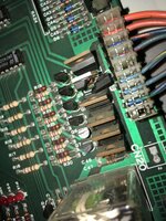
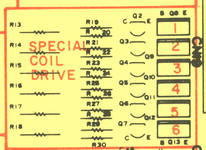
Thanks @pinballmania had a try probing via the above method, nothing was seemingly at fault from the CN19 connector side of things (This could just be me being a muppet, this is creche corner after all 😧) So I removed the CPU and multi metered all the Transistors, and resistors from the rear of the board, in the Special Solenoid section:

SCD.png
Q8-Q13 all similar sensible readings surprisingly.
The next row though Q3 was dead, Q4 was providing very low readings relative to the other working transistors in this row.
Removed both, ready for new 2N4401's if I can find any that can deliver quickly anyway. R19-R30,R13-18 all seemingly fine.

Is there anything else I should start to check on the board while waiting to replace these?
IMG_E0428.JPG

Not for one second do I believe replacing these 2 transistors will reset my issue back to where the first issue begun.
I've come across this ten year old post, DESW Slingshot Locking on @Snux appeara to have a great understanding of the Special solenoid aspect of the board.
Hopefully the conclusion of this won't be the same as that particular issue.
 
Is there a connector plugged into cn18?? We are in system 11 land here and if cn18 is used then we are in system 7 land really with direct activation special sols .

The reason this matters is a stuck switch on a sling or pop bumper is going to be bad and cause a locked on coil. These early special sols are NOT cpu controlled because it was felt at the time cpu control would be too slow. There will be 2 switches per mech, one for score and one to activate the mech

So when you change those transistors check all the switches on the mechs. ( And of course the coil and diodes to)
 
Back
Top Bottom