What's new
Pinball info

Register a free account today to become a member! Once signed in, you'll be able to participate on this site by adding your own topics and posts, as well as connect with other members through your own private inbox!

PSB capacitor question

Andy_B

Site Supporter
1 10 Years
Joined
Oct 12, 2014
Messages
537
Location
Worksop, Notts, UK
I know my way around basic electronics and what simple components do but this has me scratching my head.

I am re-capping the PSB for taxi and have removed C9 1000uF 25v axial capacitor.

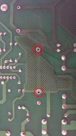
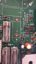
What I don't get is that both sides of the capacitor are connected to the same trace (circled in red on the images).
There is an option to fit a radial capacitor but in that case one of the legs is connected to -12v.

Can anyone explain?[emoji846]e2fa6579713e4dbdb5cb23deae69270a.jpgcfee1b6c5aa282ec552d4d8f3369b58d.jpg
Sent from my SM-G960F using Tapatalk
 
That's wrong by the looks, use the hole below the red circled in the firs pic for axial
 
Ooookaaaay!

So maybe, just maybe, someone has cleared the solder from the wrong hole and the clipped lead may still be in the -12v trace.

Just maybe[emoji1]

Sent from my SM-G960F using Tapatalk
 
That must've been wrong all along, or since it was fitted. I see either type as having its -ve in the -12v pad (the lower half of the white circle). The +ve would be in one of the red circles - a Radial in the lower, and an Axial in the upper. The two white outlines show the footprint of the two types.
 
1630591847065.png

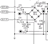
Please verify..... However if i have the right cct diagram then one pad should be directly connected to TP4, the other to TP2....
 
Going by the diagram and Andy's picture, the pad in the lower half of the white circle, still filled in on Andy's board, is the -12v rail, with TP4 nearby and the correct spot for a capacitors' -ve lead. The two cleared pads must be the points for the +ve lead of C 9, either radial or axial type. An axial capacitor between those two pads would be redundant.
 
Last edited:
Looking at the bottom of the board it does appear there is some remaining component leg in the solder blob on the -ve through hole.

We need a before picture, I suspect as mentioned above somebody has cleared the wrong hole :tut:
 
Just positing, perhaps an original fitment radial component broke, at the -ve lead. Removing it left the lower +ve pad clear, and an axial replacement was used. Guided by the rectangular outline, the upper +ve pad was opened (it would've been needed for an axial item), and the new component mistakenly fitted between the two. Leaving the -12v rail without benefit from it, until Andy notices and raises this query.
 
Back
Top Bottom