So, after a night of hammering CV the pop bumpers decided to pack up. After some poking around, it was clear i was in for a long, tedious rebuild. Fortunately, i had all the parts to hand required to fix it up so i got to it.
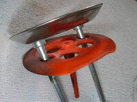
The driver board transistors that control the top and middle pop bumpers (bottom one is the boom ballon - rebuilt that a few months back) were fried and needed to be changed out. Not only that, but the pop bumper wafers were damaged, as were the fibre/metal links that connect the push rods to the solenoids.
Here is a pic of the wafer damage:
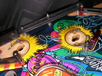
Grubby pic of underneath the bumpers:
Anyway, the driver board had to come out. .... Once out i changed the two transistors (Q47 and Q67) i had to then replace the driver board and then get to rebuilding the bumpers.
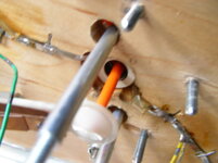
The pop bumper illumination on CV (and many other dmd era games) gets power from two long, flat bladed prongs that feed thorugh the pop bumper base, and under the playfield. They are then stapled to the underside of the playfield, making them a bit of a pain to refit. This means you will have to cut the prongs and fit new lamp sockets to rebuild your bumpers.....


If, like me, you dont have any new lamp sockets to hand, and dont have access to a staple gun that can fit between oodles of wiring and mechanisms, you can pry apart an IDC connector and use one of the metal tabs that is inside it to form a connection 'bridge' with your old, recently cut lamp socket prongs and the part of the prong that is still stapled to the underside of the playfield. Just snap the IDC pin in half, flatten the pieces with a pair of pliers, and use one for each side. Solder to the lamp socket and stapled section underneath, and done! Heres a crap pic showing the completed job:
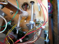
Some genius also decided it would be a good idea to place non removable washers on the end of the bumper push rods. This means you cant remove the push rod unit as it wont fit through the playfield holes with them fitted: Pic shows the non removable washers on the end of the rods:
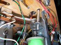
My solution to this is quite an easy one..... Crush them with a big pair of pliers till they thread through the holes nicely
 :
:
For refitting purposes, any washer that fits over the threads and mates up to the rod without sliding over the top will do. (3.5mm internal diameter washer works great) Easily found in any B+Q or other hardware shop. The washers need to be a decent fit as the rods are pulled down on the fibre links as the solenoid energizes.
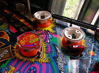
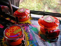
Ahhhh....Happy bumpers at last
 :
:
The driver board transistors that control the top and middle pop bumpers (bottom one is the boom ballon - rebuilt that a few months back) were fried and needed to be changed out. Not only that, but the pop bumper wafers were damaged, as were the fibre/metal links that connect the push rods to the solenoids.
Here is a pic of the wafer damage:

Grubby pic of underneath the bumpers:

Anyway, the driver board had to come out.
The pop bumper illumination on CV (and many other dmd era games) gets power from two long, flat bladed prongs that feed thorugh the pop bumper base, and under the playfield. They are then stapled to the underside of the playfield, making them a bit of a pain to refit. This means you will have to cut the prongs and fit new lamp sockets to rebuild your bumpers.....
If, like me, you dont have any new lamp sockets to hand, and dont have access to a staple gun that can fit between oodles of wiring and mechanisms, you can pry apart an IDC connector and use one of the metal tabs that is inside it to form a connection 'bridge' with your old, recently cut lamp socket prongs and the part of the prong that is still stapled to the underside of the playfield. Just snap the IDC pin in half, flatten the pieces with a pair of pliers, and use one for each side. Solder to the lamp socket and stapled section underneath, and done! Heres a crap pic showing the completed job:

Some genius also decided it would be a good idea to place non removable washers on the end of the bumper push rods. This means you cant remove the push rod unit as it wont fit through the playfield holes with them fitted: Pic shows the non removable washers on the end of the rods:

My solution to this is quite an easy one..... Crush them with a big pair of pliers till they thread through the holes nicely


For refitting purposes, any washer that fits over the threads and mates up to the rod without sliding over the top will do. (3.5mm internal diameter washer works great) Easily found in any B+Q or other hardware shop. The washers need to be a decent fit as the rods are pulled down on the fibre links as the solenoid energizes.
Ahhhh....Happy bumpers at last


