What's new
Pinball info

Register a free account today to become a member! Once signed in, you'll be able to participate on this site by adding your own topics and posts, as well as connect with other members through your own private inbox!

Pin-Logic High Voltage Regulator - Got or Seen one?

Nedreud

Registered
10 Years
Joined
Feb 12, 2013
Messages
3,092
Location
Aldershot, UK
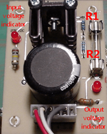
I'm curious about the "High Voltage Regulator Bally and Sterns Solenoid Driver PCB" available from Pin-Logic for $34: http://www.pin-logic.com/index.shtml#power.
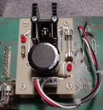
upload_2015-10-27_13-4-43.png

It's purpose is to replace the 14-18 components of the +190 VDC REGULATOR on Bally SOLENOID/DRIVER boards that is used to supply the high voltage required by the original gas discharge 7-segment displays.

Using a bit of "Google Magic" I found an old page on pin-logic.com that is no longer linked from the main wesbite:

http://pin-logic.com/hivolt.htm

A lot of the images are missing and it's very 1997 but on there it mentions:

How about designing an IC that contains all of the circuitry needed to regulate 230 VDC down to 170-180 VDC and put it all in a TO-220 package?

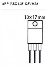
pin_logic.com_hivolt_files_image008.jpg

This Voltage Regulator IC, used in a simple circuit, can produce a steady 170-180 VDC that can easily feed up to 7 Bally displays under any load

That image led me to find the Texas Instruments TL738 (http://www.ti.com/product/TL783) which matches the 1.25-125V 0.7A specification.

The bit I'm confused about is how this device can regulate 230V down to 170-180 as it has a maximum output of 125V? And no, I can't find a similar device with a higher voltage rating!

Any techno-geeks have any ideas? @lukewells, @myPinballs?
 
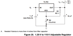
The TL738 is adjustable by using a resistor divider, which if you exclude the fuse and 2 diodes with their current limiting resistors (the brown ones) all that's left is a simple 4 component high voltage regulator like the sample circuit shown:

upload_2015-10-27_17-6-48.png upload_2015-10-27_17-8-17.png

The issue is that TL738 is only rated for up to 125V output so I fail to see how this device could be used to generate a 170-180V output. Thing is, I can't find any similar device with a higher rating, say output up to 200V. Maybe there are other components on their device mounted on the underside or on the other side of the heatsink? Still can't find a sample circuit with such a low component count capable of delivering the required voltage and current (about 200mA - there are devices that will do up to 400V but can only supply 10mA).
 
Oops. TL783 ;)

I think I've worked it out. The adjustment is that the output can be between 1.25V and 125V below the input voltage. I noticed that the ROTTENDOG BPS022 board, which is a complete replacement for the SOLENOID/DRIVER board, contains a similar circuit based on an LM317, a similar device with a smaller range of 1.25V to 37V.

I am however quite surprised that neither the Rottendog, ALLTEK or Pin-Logic boards have a trimmer to adjust the output voltage. The Rottendog states the input voltage is 200VDC and the maximum it's LM317 will adjust is 37V so its output could down to 163V but an original Bally transformer kicks out 230VDC for this circuit (as indicated on the Pin-Logic board) so could be 193VDC or higher. None of these devices compensate for the input voltage (as best I understand them). They kick out what you put in minus a fixed amount.
 
Correct, it is only rated for 125v, but that means, it cannot be allowed to see more than a 125v difference between vin and vout

So if you put 230v in and set 190v out, then thats only a 40v potential difference between source and output. This woks because the io's are floating and there is no reference to ground.

This is a common trick that people (such as Rottendog) use on their power supplies, to basically save money and build a cheap HV circuit. Now there is an accompanying protection circuit that you are supposed to include in your design to protect the regulator under a fault condition, but again (I guess to save money) I have not seen this implemented on any of the common replacement power supplies.

As people who own Rottendog supplies know, if you ever short the HV output by mistake, or if the display starts outgassing and increases it's current draw, it will eventually pull down the output voltage to the point where it exceeds the maximum voltage potential rating and the HV regulator explodes
 
Thanks @lukewells, you have gathered and written down all the disconnected bits of information that were floating around in my head after reading the TL783 and LM317 data sheets, and reading over some sample/practical circuit designs.

The fact that all these boards seem to have the barest minimum component count seemed kinda scary. None of them have even the most basic protection of a diode or any input-output decoupling or bypass caps for noise filtering etc.

I was just intrigued that the rather complex original Bally circuit (complex even by late 1970s standards because of needing to handle massive changes in current as displays flash from full off to full on in test mode) could be reduced to just 4 components. In practice it seems you can but in the long term it may not be the best solution.
 
I looked at these too,but in the end I just did a complete HV section rebuild using a BUX84 on the couple of dodgy SDB's that I had,they all work fine now
 
Back
Top Bottom