What's new
Pinball info

Register a free account today to become a member! Once signed in, you'll be able to participate on this site by adding your own topics and posts, as well as connect with other members through your own private inbox!

Pictures of BK 2000 underside of the play field

GrizzlyNate

Registered
Joined
Dec 15, 2024
Messages
52
Location
Texas
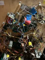
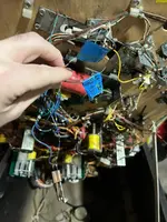
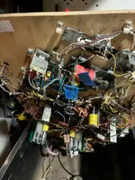
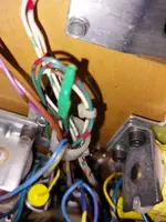
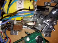
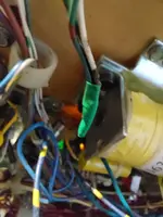
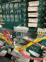
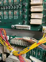
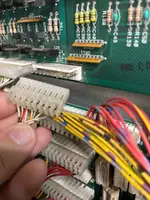
I have a BK 2000 I am working to restore. I have worked on the mpu to get the pin to boot up. I have a ton of relay switches not reading though and both the right flippers not working. When I look under the play field I can tell one of the lamp relay boards is missing so working to replace it. However, I have a green with reddish purple stripes not connected to something and a white and black wire as well. I have figured out one of the green purple is the connection to the rest of the switches I think to the right side but something is missing that they all should be connected too. I also have a switch just dangling and can not figure out where it goes. I am just asking for some underside pictures of the front of the play field to figure out where these wires connect so I can fix that and then start addressing why certain switches are not working. I know the start button switch as well is not registering so this lets me know I have other issues but got to get it all connect first to start tracking it down.
 

Attachments

  • IMG_5171.webp
    IMG_5171.webp
    119.3 KB · Views: 26
  • IMG_5170.webp
    IMG_5170.webp
    77.9 KB · Views: 26
  • IMG_5169.webp
    IMG_5169.webp
    100 KB · Views: 26
Nate, from memory there is meant to be a playfield slam tilt switch in that location. When I got my bk2k mine was missing and I never reconnected it.
 
Hello, Nate,

The serious-looking switch you have simply dangling belongs on the right-hand flipper; the plastic triangle bears on the flippers' regular End-of-Stroke switch, so that the flipper linkage pushes open the EoS as intended, and also closes the additional switch to operate the upper flipper. Williams often/usually switched extra flippers from the button switch(es), but Black Knight 2000 was an exception. The flipper assembly may have lost the longer screws needed to fix the two switches, unless they've been fitted regardless, and damaged the coil..

The U.K. allocation of this game didn't have a playfield tilt switch, but the wiring was provided, with the mounting point for the switch bracket dimpled on the playfield. I see two Green-red wires loose, I'd join them together to have continuity for that switch line, Column 2, which also serves the outhole and ball trough switches. Having those not showing would prevent starting a game, though I'd half expect a display message about balls missing.
 
Last edited:
That explains why my bk2k came without the playfield tilt switch. It's the same on yours Nate. From the switch matrix the plafield tilt is switch 9 and is green/red and white/brown wires. So just tape the ends of those two up separately and tuck them in the wiring loom.

Edit for clarity As Jay Walker states tape the green and red wires together for continuity but keep the white/brown wire separately taped.
 
Last edited:
Pics of isolated switch wires - >I always use heat shrink rather than tape for a neater finish. Plus also what the right flipper switch stack should look like. The manual only lists the shorter screws as #5 5/8". It doesn't list the longer ones which are needed. If you don't have the longer screws just add the height of the second switch that is dangling to the 5/8"
 

Attachments

  • 20241221_103508.webp
    20241221_103508.webp
    87.9 KB · Views: 23
  • 20241221_103342.webp
    20241221_103342.webp
    193.7 KB · Views: 23
  • 20241221_103418.webp
    20241221_103418.webp
    64.1 KB · Views: 23
  • Like
Reactions: JT.
PS. I converted my flippers to the newer style external springs. Yours may have the earlier conical springs that go around the plunger.
 
Asia and Jay,

Thank you both for the input. I will be getting those wires and the flipper switch fix tomorrow. I’ll try to start the game again and see what I have. Maybe back as to understand if certain switches are still not showing as being activated. The other thing is from the person I got it fro
Said the right flipper did it work. Not sure if that was too flipper or both. I know right now when I click the flipper button it does not fire. Once all in place I’ll get some v measurements as I have leaned it’s best to start there. I did a trace on the wires and they do go back to the mpu and power board for continuity but that just lets me know wires are connected.

Aisa is it hard to convert the springs? This is something I might look at down the road.
 
Nate,

There are two copies of the manual available on ipdb. One doesn't show the additional switch on the right flipper, the other (possibly a later edition) does, with the screws listed as #5 x 1-1/4.
 
Nate,

There are two copies of the manual available on ipdb. One doesn't show the additional switch on the right flipper, the other (possibly a later edition) does, with the screws listed as #5 x 1-1/4.
Yes, I have learned that. The manual I got with the pin is the first version but the pin playfield is the second version. I have learned this due to one of the relays on the first version swapped to a different kind. Just working backwards now and learning how to look at the switch matrix and diagnoses the ones not registering with DMM. All good as I’m just learning new skill sets. Thanks for all the info
 

There is a great write up and video on diagnosing switch matrix issues here.
Thank you very much. I will give it a read. One of the hardest things Is just understanding it all. Do you happen to have any write ups on building a test bench. I seem to always come up short on that as it’s not very straight forward. No step by step guides.
 

There is a great write up and video on diagnosing switch matrix issues here.
Ok so I had a quick question for you on this as I am totally kinda lost now. I read and watched the video to understand the switch matrix. I did the continuity of all the wires and followed them along on the switches and get the beep sound on the DMM. I go into test mode and can only get the switch read for Left outline #39 and left return lane #55. I did a pulse test but unsure what I am looking at for that as I touched the logic prob and got high on one leg and low on the complete opposite leg and a high pulsing beep on the middle leg. I am doing more reading and watchin but a little lost as that is a lot of switches not registering but a lot seem to be pulsing. Just figured I would see if you have any advice on the best way to approach it. I'll keep working on it just asking to make sure I have not missed something simple.
 
When I am diagnosing multiple switch matrix errors on a machine new to me I start by printing out the matrix and marking on it exactly which switches are working and which are not. Use the diagnostic switch tests for this. Plus also mark which switches are triggering others (I use arrow markings for this) Usually with all this information in front off you it is easy to work out where the faults may be and follow as per the guide I linked to.
 
When I am diagnosing multiple switch matrix errors on a machine new to me I start by printing out the matrix and marking on it exactly which switches are working and which are not. Use the diagnostic switch tests for this. Plus also mark which switches are triggering others (I use arrow markings for this) Usually with all this information in front off you it is easy to work out where the faults may be and follow as per the guide I linked.

So I may start a new thread but I am lost for sure. Could game Tom go bad or is always switches are due to switch board issues. I have checked the wires and they are all good. I go into switch test and when I push a switch I hear the sound of something buzzing as it’s making connection and sending a signal back. The person I got the pin from sent a video of it all working but I have to replace several chip sets as they took them away to fix other pins. Could a game rom go bad? Just strange as I am getting pulsing all the way back to the pin them selves but nothing is reading. Figured I would ask on the game rom as I continue to work on it.


You can buy a switch matrix tester which will give you a definitive answer as to whether the problem is with the board or the wiring or you can simply disconnect the switch row and column connectors at the board and test each row and column combination in turn with a jumper wire. If nothing changes the fault is on the board. It may well be on the board as you have already said that the game came to you with a non working board. But you say you have pulsing and 2 of the switches work so it could also be a connector issue so I would be looking at tracing all the wires right back to the board including the interconnect board and checking each connector and its pins on the boards to make sure they are not loose corroded or have battery leakage damage.

Golden rule of pinball repair is to check all the simple stuff first like wiring, loose connectors fuses etc.

Also can you post a pic of the main board and its switch matrix connectors as sometimes faults are obvious to see particularly battery leakage damage.

I really don't know why anybody would raid parts from a decent working board. Usually that is reserved for irrepairable damaged boards.
 
Switch matrix connectors are 1j8 and 1j10.
I will get pictures in my morning and get them posted tomorrow. Also need to make sure what I am seeing is a pulse. I hear a noise and my logic probe seems to be pulsing but also new enough I could be wrong. Looking up that video as well. I fully understand not taking things off good working boards but I think its a situation we’re the person was stumped on getting the right flipper to work and needed to things for another machine. Speaking of taking from non working boards I am also going down a road to remove and clean acid small acid dmg on a non working board and putting new components on it. Maybe a lost cause but just trying to learn all I can. Pics incoming in about 8 more hrs or so.
 
The switch circuitry is directly under the batteries so is right in line for battery leakage damage. It's usually a load of work fixing this and some of the board traces are very thin so damage easily and any battery leakage will run under the chips so they should be removed to clean up. None of this is commercially viable but OK as a hobbiest challenge if so inclined. Personally I don't bother as a new board is cheaper than my time.
 
But do send a photo and check simple stuff first like connectors and associated pins for corrosion before diving into board work.
 
  • Like
Reactions: HHH
But do send a photo and check simple stuff first like connectors and associated pins for corrosion before diving into board work.
Ok so finally got back out to it. Wires are all flowing as connected and when I logic test 1j8 all pins show a pulse from the logic probe. I am reading to learn to check the row for the return so I can do that. If I have a pulse on return then I am going to be stumped for sure.
 

Attachments

  • image.webp
    image.webp
    119.2 KB · Views: 11
  • image.webp
    image.webp
    101.8 KB · Views: 11
  • image.webp
    image.webp
    75.7 KB · Views: 11
Do what @Asiapinball said go into switch test, disconnect the row and column connectors, put a wire on column 1 and touch it to all rows. Then move on to the next column and so on. You should be able to see all switches on their own this way. If you get multiple activations or switches don't work you have an issue in the backbox. If that works, put the connectors back and proceed to testing switches one by one as described above. No use logic probing the pins I am afraid.
 
Ok so still following and was able to get some time to get back at it. Have done the test where I jumped the switches from 1J8 to 1J10 and all switches that way light up on the display as being read. I went back through and check wiring and all wiring have continuity from each point back to the correct pin on 1J1 and 1J10. Continuing to work through the write up but wanted to report back. Thanks again.
 
  • Like
Reactions: HHH
Ok so if all the columns and rows work with the Jumper method then that would mean the board is fine? If all the wires so continuity then the wiring is fine? Here is what I have done and have read and re read the info provided but now I am at a loss. Any direction or ideas are greatly appreciated as normal. I have checked the wiring for all the switches on the matrix and all have continuity back to each pin based on the color for the Column and the Row. I have them proceeded to use the jumper method to verify that the display in switch edges will report back if the switch is closed. When I do the jumper method all of the switches report back as being closed. When I hook the wires back up I only have two that show up in the switch edge test (48 and 53). Another thing I have noticed when I am in the switch edge test and press a switch I can hear a hum as if the switch is closing and voltage is going forward but I am not getting a reading of the switch closing. When I received the game I did have to replace (U15 and U24 w/ IC 6802, U10 and U9 w/ IC 6821, and U25 with a NVram). The board is free of corrosion as I knew to look for that just based on battery location. I am at a loss as if the jumper method works I would think the board is fine but with the wires all having continuity I am thinking that part is fine. Any thoughts on what to look at next is greatly appreciated.
 
The jumper tests you did show the main backbox board is OK. The fault is in the wiring to the playfield. The wires go from the main board through the backbox interconnect board (lowest in backbox) and then onto another interconnect board under the main playfield bottom left corner when mainplayfield.is raised. Check pcb connector pins and connectors at both interconnect boards and check for continuity from the 1j8 and 1j10 connectors down to the corresponding wire on the under playfield connector board (if you haven't done so already).
 
If you measure continuity on the cables from backbox to the switch try shorting the cables at the switch and see if that registers. If that works either switch or disode are broken or connected wrong.
 
If you measure continuity on the cables from backbox to the switch try shorting the cables at the switch and see if that registers. If that works either switch or disode are broken or connected wrong.
Ok so a little confused on this as I have checked the column wire from J8 to the correct switch on the switch matrix and have a solid beep with no issues. I have also check the row wire from J10 back to the switch on the switch matrix and have a solid beep with no issues. Would this confirm that any other wire rerouting is connected and does not have issues? aka the playfield connector board? Should I be able to test from J8 wire and push the switch down and get a solid tone (continuity) back through the row return J10? Could all but 2 switches or diodes go bad on the entire pin? I will work on trying to short the switch and report back as I was typing I was going to ask how to do this but looked it up. Teaching my self all kinds of things as I travel down this road in repairing pins and bring them back to life.
 
So go into switch test and short the cables at the switch. That will most probably get the switch to close. You then need to work out what the issue is - can be the diode or the switches being connected wrongly - the NC pin is used as a solder point, easy to swap that around - think you mentioned that someone had this one apart, may well have connected switches wrong and never fixed it. Row WHT-XX cable should go to the normally closed pin together with the non banded side of the diode. This usually is the pin on the far side of the wireform pivot. Banded side of diode goes to common (usually the pin close to the pivot). Column GRN-XX cable usually isn't soldered but has a crimp spade female going on the middle pin.
 
So go into switch test and short the cables at the switch. That will most probably get the switch to close. You then need to work out what the issue is - can be the diode or the switches being connected wrongly - the NC pin is used as a solder point, easy to swap that around - think you mentioned that someone had this one apart, may well have connected switches wrong and never fixed it. Row WHT-XX cable should go to the normally closed pin together with the non banded side of the diode. This usually is the pin on the far side of the wireform pivot. Banded side of diode goes to common (usually the pin close to the pivot). Column GRN-XX cable usually isn't soldered but has a crimp spade female going on the middle pin.
@Asiapinball will have to start working backwards through the boards to see where the break is on the board. The jumper test did not short out the switch so there has to be a break in those wires some where. Is the best way to test this use a logic prob and follow a pulse all the way through to the switch? The continuity test showed that both wires at the switch showed connected all the way back to J8 and J10.

Thank you both for taking time to answer the questions as I have a big restore planned for this pin once I get it working.
 
Back
Top Bottom