What's new
Pinball info

Register a free account today to become a member! Once signed in, you'll be able to participate on this site by adding your own topics and posts, as well as connect with other members through your own private inbox!

Complete Not pinball….but interesting. early pong - computer space ball

AlanJ

Site Supporter
Joined
Dec 27, 2017
Messages
7,763
Location
Leeds, West Yorkshire
Alias
Alan
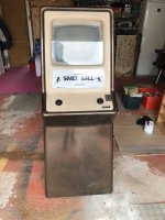
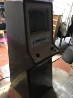
I’ve got a piece of arcade history here with me, belonging to @Jagspete.

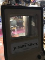
It’s a 1972/73 Nutting Associates, “computer space ball”, which is, actually a version of the famous atari pong. Nutting Associates are credited with the first commercially available arcade game, “computer space”. If you’re into this sort of stuff it’s worth a google / wikipedia. lots of crossovers with the other pioneers and atari etc.

37CB85E3-8589-49E2-A4F9-9E023FB54B03.jpeg
8245D9C6-8D03-4B3D-8CC4-8D91FA2CC40E.jpeg
6D1C8A48-6831-42DC-BF39-0162F7FBD7B7.jpeg

Inside
B2E3C048-7AE8-4B3F-904B-BC0538EC1607.jpeg
2C85151E-3367-49D7-82B2-39BB6CFC3AD7.jpeg

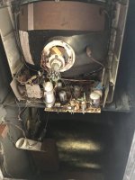
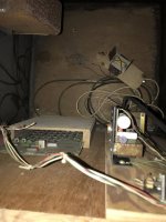
So it consists of an off the shelf b&w valve tv, a power supply board, a circuit board, a coin mech, two potentiometers and a play counter. that’s it

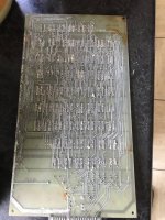
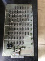
There is no computer in it, despite its name, it’s just discreet logic chips:
38DF2D95-4667-4B3B-87B4-701BF1BB6782.jpeg
FD4D3590-024E-4C9D-8CC9-9886F88E4CD7.jpeg
The board has maybe some damage.

There was some documentation and schematics with the machine, but unfortunately there is no schematic for the logic board.

A scan of the internet hasn’t yielded one, but I got 1/2 a clue on one site I found that suggested maybe using the atari pong schematic as a guide, as this is possibly the same or very similar design.

I’ve got the atari schematic, but it’s poor scan quality and difficult to understand.

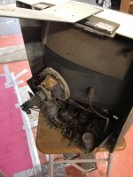
I also received, a second unit consisting of tv, poster board, wiring and coin mech, play counter. Sadly no second logic board.
 
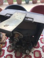
First job this aft was to take it all apart
1E54681F-A43D-470B-B170-4518EFC182DB.jpeg
6B53C893-D40E-462C-B363-BD5071B3F5B4.jpeg
42012C90-05ED-4962-BADD-064A7D047972.jpeg
CBB85D9F-EA50-4123-9A93-CF145D305E6A.jpeg
1F314CCF-B0D4-48EA-A2E9-BD8D89EA3ED6.jpeg
4B33E41B-B7B7-42A2-A12A-C6F50A931289.jpeg

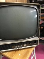
The monitor is an off the shelf tv, still in its original case but with the back removed.

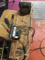
I tested out the power board first. I replaced the 15a round pin plug with a ‘modern’ 13a square pin 😂.

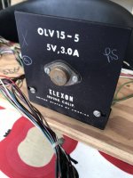
tested continuity and checked the transformers for shorts. all looks good. Plugged in. nice- i got 120v from the first transformer and 5.2v dc from the rectifier board. No ac there so looks pretty good. The other unit has a really exploded capacitor, so I’ll run with this one instead.

Next, A lot of pre power tests on the tv monitor. Not many big caps, but the big one is a bigger. looks ok and seems to test out ok.

There is two flying wires out of the back of the tv board- at first o though this was a power connector but it’s not. I spent ages tracing the circuit and it is part of the heater circuit for the valves. there is an external power resistor on a heat sink, so looks like tgat needs to be connected up in series with the valve heaters. I wired it all up and plugged in.

Nothing from the valves. but on a plus side, i got sound hiss, touched the sound input and got some noise, which is good.

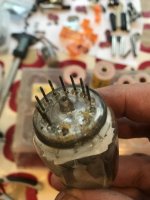
traced the valve heater circuits and found this
23D360D0-F07A-4FF9-9530-E6D9F6A517FC.jpeg
it’s the high voltage diode. it’s lost two pins which are the heater circuit.
I went to try the valve out of the 2nd tv, it’s knackered too, it has all its pins, but the heating circuit is blown.

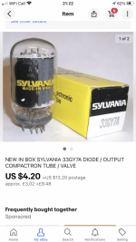
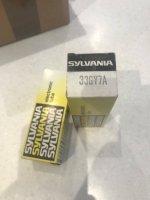
Managed to find two on ebay, in canada:
8D2C3930-EF56-4F60-AC9C-2605B9BDA9BC.png
£25 for two plus probably get hit for some import duty etc.

So i can’t go further with either tv until they arrive. I tested all the other valve heaters and the main crt heater and they’re all good.

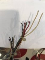
Tomorrow I’ll figure out how to wire up the logic board. the edge connector has been cut off the wires, but i can pinch the connector off the 2nd unit.


17F3D656-0FB5-495A-B561-0E7CD64A08A9.jpeg
548FA85D-28F5-42B6-A964-CC04D46D71A7.jpeg
 
Yup - those two missing pins on the GY7A wont help... they are the feed for the heater :D
 
I have been trying to source spare parts for this, but unfortunately most stuff is unobtanium. There are a number of flaky components on the tv chassis, eg the extra high voltage coils. There are none of the TV 📺 sets around anymore. The game uses a 15” size TV which is a pretty uncommon size back in the day. There is a 9” and 12” model that uses almost same chassis, but only found one of those for sale in USA and is $$$ to purchase before shipping and import VAT etc, so would only be a very last resort. can’t find anyone in usa with spare parts for these, but will keep looking…….

Next week I’m going to hook up the logic board to a test rig and see if it still works.
 
I’m assuming that is a B&W tv?

It’d be worth posting this on UKVAC as there are some old B&W enthusiasts over there who may have some leads for you. Either way, they’d enjoy your shop log.
 
I am trying to keep it all original. I was hopeful that I could get at least one of the two tv sets going, but they both have similar issues. Fingers crossed though.
 
LEt us know what parts you are trying to locate for the Chassis Alan... Maybe one if us can find it... somewhere... :D
 
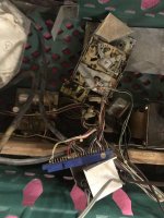
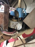
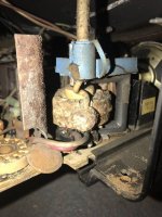
Thanks @Paul I’ve been cold testing today, I’m concerned about the integrity of both of the TV’s EHT coils. they are crusty and falling apart
1D418799-A612-47CF-8500-5C710332FB90.jpeg
64BDF4D4-A32E-4FB7-B396-012116894B74.jpeg
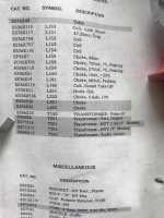
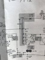
Luckily the thing came with a schematic and parts list for the chassis.
47E13435-6A89-49C2-AE9A-AB585C7E1387.jpeg
E792FD07-12A5-4FDE-AD52-33AA305C3264.jpeg
I have tested out the coil and it seems ok, but then when you consider this thing is handling 13,000v it needs to be bob-on.

I’m happy to try these existing ones out, once I get the new valves, what’s the worst that can happen - I might make my hair stand on end!!!
 
Ahh yes... completely see what you mean! That looks dubious at best... Saying that, it's the casing.. but if it wasnt needed then it wouldnt be there!

Parts list doesnt really help either... "Transformer HVT"...

Are you aware of anyone that has done any work on these at all? Might be your best bet!
 
I used to repair tv's back in the day and that lopt will definitely need replacing as the insulation is pretty much key as they deliver around 14kv on a b/w tube i would guess the valve driver may also need replacing. i will ask my dad as he was a tv engineer for about 50 years
 
I used to repair tv's back in the day and that lopt will definitely need replacing as the insulation is pretty much key as they deliver around 14kv on a b/w tube i would guess the valve driver may also need replacing. i will ask my dad as he was a tv engineer for about 50 years
I've got new valves on order as both tv's have knackered ones. Yes, dont hold out much hope for the transformers. 13kv it states in the schematics. Really needs some good insulation!!!
 
I've got new valves on order as both tv's have knackered ones. Yes, dont hold out much hope for the transformers. 13kv it states in the schematics. Really needs some good insulation!!!
I think that they used a few different brands of tv in the old machines, i would personally look for a same size vintage tv and swap the board and tube as the caps and resistors are also likely to be out of tolerance. That said we know you like a challenge Alan,
 
I've got new valves on order as both tv's have knackered ones. Yes, dont hold out much hope for the transformers. 13kv it states in the schematics. Really needs some good insulation!!!
yes you used to be able to light your fag from the spark from the lopt cap :D
 
I've joined a UK tv repair forum and got some useful help on how to go about fault finding the tv screens. Still waiting for the valve tubes from USA. In the meantime more research.

On the logic board, I hooked it up and tried to simulate starting a game, but it doesnt seem to be doing much. I guess that a number of the ics are faulty. It would be really nice though to get the tv working, so I can hook it up properly, so I'm parking the board for the time being.
 
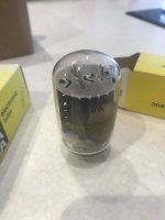
These arrived from Canada today.
CEE92A1D-5A19-407B-A543-3C7BC8CF42EA.jpeg
9B8C899D-2831-458A-943D-B71A89E61ACF.jpeg
So I can get on with the tv repair side of this project.

Whilst I’ve been waiting for these parts I’ve been doing a lot of testing on both the TV sets. One of them had another broken valve, I only just spotted that the other day. I’ve tested as much as I can, and happy to plug the new valves in and give it a whirl.

On the logic board side, I connected it up to a nice good 5v dc supply and probed a few of the components. It doesn’t seem to be doing much at all, it should be doing something because on power up, it is supposed to go into “attract mode”. I don’t have a proper schematic, but the Atari one is very similar in terms of the logic chips used. I’ll come back to this board later.
 
So one step forward , i’ve managed to get one of the tv sets going. it lights the screen up and shows some sort of picture frame. it’s not perfect but can be worked through now to improve it.

One step standing still, the logic board is doing nothing at all. I bought a new edge connector and wired it all up and connected to the 5v power. it’s not doing much at all. logic probed a few chips at random they have power but nothing is pulsing or counting. tried to simulate dropping a coin in and again nothing. the board is corroded, rusted - nasty looking. I’ve checked a few key traces and they actually seem ok, but it’s a mega job to check all the traces for opens and shorts as well as 66 chios any of which could be dodgy.
 
Wow, very interesting, I wouldn't know where to start. Good luck with the board
 
I have attached a redrawn schematic of Atari Pong. I didn't draw it so take it for what it is, hope it helps.

I would start by ensuring you have EXACTLY 5V at all chips. These boards were notorious for being super sensitive and sometimes 4.9V wouldn't cut it!

Second make sure the oscillator is running before doing much else, logic probe or oscilloscope should help here.
 

Attachments

  • PongSchematic.pdf
    165.6 KB · Views: 13
Back
Top Bottom