No worriesNot sussed those ones out yet, there's a bit of a long queue here -- been prioritising those that aren't mine

Well one of them probably doesn't have a fault I think it was the actual pins on the connector block, be interesting to know, (dont worry I don't care if it works fine
)The other acting as node 9 is definitely a cap issue not holding its charge to start the board I suspect, as it will work once machine on for a bit and a charge has been put through the cap, quick turn off and on again works perfect, until powered off for a bit.


")


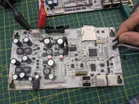
 I did consider wiring that in, but reverted to just using the serial console as this board isn't mine. This required clearing 3 through holes (since they didn't populate that connector either!) and soldering 3 standard 0.1" headers. A USB to UART adapter got me into the console which helpfully includes a login prompt, and editing /etc/passwd to remove the root password allowed for easy login (the default password of "pinadmin" somehow didn't seem to work).
 So now I'm using `arm-linux-musleabi-gcc -march=armv5te` and finally we can run our test code!