What's new
Pinball info

Register a free account today to become a member! Once signed in, you'll be able to participate on this site by adding your own topics and posts, as well as connect with other members through your own private inbox!

Newbie with Firepower Issues

Bulla

Site Supporter
Joined
Aug 13, 2022
Messages
58
Location
Buckinghamshire
Can anyone help with a few Firepower questions please ? Go easy on me I’m new here !

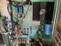
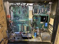
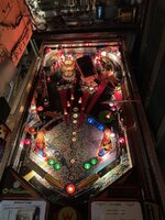
I recently lifted the playfield to change some bulbs and since putting it back I’ve got nothing from either flipper. Game starts ok and I can plunge the ball in play but flippers are dead. I’ve checked all fuses in the back box for continuity but not sure where to go from here ?

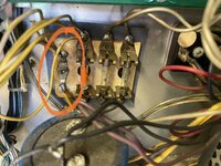
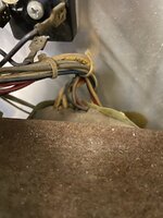
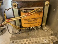
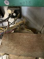
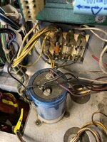
Speaking of bulbs, I’ve got most of the GI in my back box out. Is there anything else apart from fuses to check before replacing connectors ? I understand this could be a burnt connector ? I think I’m right in saying people recommend swapping these older style connectors for molex instead ? Can anyone tell me which part number I need to replace these ?

Thanks for any help !IMG_0695.jpeg
 
As long as there not bodged together with solder or burnt and look in order then no reason to change the connectors IMHO.
 
When I got my Firepower the multipole connector to the backbox panel was burnt around the GI wires but they had already been separated out onto their own connectors, so you may have to do that to yours if you intend keeping the old GI lamps (LEDs will save your backglass though)

Your flipper power comes from the connector bottom left on the Power board, check for a loose crimp on that.
 
Resistors look toasty, probably need changing. I am round the corner in Bucks so can sort that if you want.
 
Hello,

The corner of the 'driver board' shown in your picture isn't anything to do with General Illumination, it's the section controlling the 'Lamp Matrix' or feature/insert lamps; the individually controlled lamps such as F-I-R-E lanes, Bonus Multipliers, 1 to 6 Arrows, the shrouded 'dashboard lamps' such as Shoot Again across the bottom of the backglass etc.

FirePower doesn't have any method of switching the general illumination, e.g. the larger part of the lamps behind the backglass, coin slots, in the slingshots and under the decorated plastics. Even if the computer side didn't start up, the general illumination should light when the mains is On. As I recall, the circuits use Yellow and Yellow-white wiring, and are fused by one of the three fuses on that bit of tag-board.

It seems that you've not lost solenoid power, as a ball is served out. The solenoid power has two fuses, one for flipper solenoids and another for the rest. Does the flipper relay switch on with a click when a game is started?
 
Last edited:
Thanks All

I think this may be the relevant GI connector off the power board ?

Screenshot 2023-08-22 113144.png

I'll check for clicks on the relay and double check fuses .
 
Yes, G.I. comes directly from the power board and should be always on as per what @Jay Walker wrote above. The header solder joints like to crack on these old boards and the connectors love to burn up. The board edge connector is also a likely failure. Follow the advice by @Jay Walker first and see, if you have power at the flippers when a match is on.
 
Quick update, the fuse hiding (see below) has blown. Not sure if that’s GI or Flipper related but either way need a new one, looks like AGC20 fuse
 

Attachments

  • IMG_0707.jpeg
    IMG_0707.jpeg
    265.4 KB · Views: 18
Last edited:
Yes, the fuse shown is for the flipper solenoids; on the power supply board the fuses (from left to right) are *flippers *other solenoids *matrix/feature/insert lamps *display power rails *5v power regulation.

Being a two flipper game, Firepower is listed as requiring a 10A fuse for flippers. Before replacing it, try (with the mains Off) measuring continuity/resistance between the flipper power feed from the power supply board (Blue wires, pins 4,5,6 & 7 of the connector in the lower right left corner of the board, 3J3) and their returns from the playfield/cabinet buttons, the driver board connector 2J12, pins 1 and 2 (the second connector down on its l/h side, Orange-violet and Orange-grey wires). You'll need to press the buttons to complete the circuits. The flipper coils don't have a high resistance, but there shouldn't be a short-circuit.

The general Illumination fuse covers all three areas shown in the excerpt above - it's placed on the afterthought-looking bit of insulating board attached below the power supply board. If the playfield and cabinet have their G/I lit, the fuse will be okay. The wooden 'Insert Board' housing the score displays has its own connector for all the circuits on it, this may be the likeliest area for the illumination circuit to have broken down.
 
Last edited:
Yep there's continuity/resistance between the Power board blue wires and the driver board orange wires if I push the flipper buttons.

I've rechecked the fuses on the insulating board and they test ok but I've got no GI in the coin door and I'm not 100% on all the GI on the playfield but I've got no plastics lit. Of course I cant be 100% it's not bulbs but I've just swapped a coin door bulb with a working one and that's not worked either.
 
Maybe it is lacking the ac power for general illumination, then. As I recall, the playfield general illumination is all lamps under plastics, such as the Red lane dividers for the top lanes, inside the slingshots, behind the centre target banks, etc, but not the Jet Bumpers. As a guide, with the front door open, press 'Advance' to stop the Game Over/attract mode; all the controlled lamps should turn off due to the machine now being in test, so only the general illumination should remain lit. If there's nothing at all, set your meter to a suitable ac voltage range, and measure between the Yellow and Yellow-white wires, or the fuse and the wire link alongside it on the little card. It should show approx. 6.5 volts. The circuit is quite basic - a transformer winding produces the ac voltage, which routes through the fuse and link to the three areas, cabinet/door, playfield and Insert board.
 
Thanks Jay

I’m not getting anything AC on a lamps with the yellow and yellow/white and assuming you mean the wire I’ve circled nothing AC on that either.
 

Attachments

  • IMG_0717.jpeg
    IMG_0717.jpeg
    182.9 KB · Views: 21
You need to measure AC across the GI circuit, i.e. the solder point and the fuse next to it. Measure against both ends of the fuse, it simply may be broken. In case this yields nothing you need to measure between the yellow lines at the transformer connected to 17 and 19. If there is nothing there you have a broken transformer (unlikely), otherwise check continuity from the board to the transformer and find the break.
 
Looking at the picture, I think the 20A fuse with the orange band, and the link alongside, have the wires from the transformer at their lower ends. The upper ends each have multiple wires, to feed the separate connectors for the different areas (7P1, 8P1 & 9P1 in the diagram above).

I think I see the Yellow wires from the transformer in the bundle entering the picture from the right - one seems to connect to the link, the other should attach to the fuseholder, but I can't really see it. Then all the Yellow feeds should be on one side, and the Yellow-white on the other. The fuse holder seems to have some ratty looking ends of wire around there, too. The Purple wires are connected to the large blue capacitor, aren't they? (they're for the controlled lamps, not general illumination).
 
Does that help ?
 

Attachments

  • IMG_0719.jpeg
    IMG_0719.jpeg
    301.9 KB · Views: 11
  • IMG_0724.jpeg
    IMG_0724.jpeg
    95.1 KB · Views: 8
  • IMG_0725.jpeg
    IMG_0725.jpeg
    224.3 KB · Views: 6
  • IMG_0726.jpeg
    IMG_0726.jpeg
    134.6 KB · Views: 10
  • IMG_0727.jpeg
    IMG_0727.jpeg
    142.9 KB · Views: 11
As per what @Jay Walker wrote, there should be two yellow cables from the transformer terminating at the fuses in the lower right hand corner of the pic. Measure between them. If you have no 6.3V there take the shield off the transformer and see if there is obvious damage to the cables. Not sure if they are coming right out of the winding or are connected under the shield.
 
Yep those two yellow wires off the fuses go into the back end of the transformer. I may need to unbolt the transformer to get a better look as it’s pretty tight round the back
 
Those two at the back are on the bottom of the orange band fuse and the bottom of the metal lug to the left of it
 
Those are the ones. If there is no AC voltage there you have a problem. You are measuring in a small selection on AC with your multimeter?
Switch machine off, take the fuse out and measure resistance across the yellow cables, should be low ohms, not open or short.
If open you can try to cut into the insulation at the transformer end to measure continuity with the machine off - but would be surprised if it is a break in the cable. You‘ll otherwise need a new transformer or a separate power supply you connect to the GI.
 
It lives !!!!!! Just popped the fuses back in before pinning the yellow lead on the transformer and the GI flashed on ! I think the fuse holder is the culprit, it looks like there is some mess of very fine wire and solder under it. I’m going to pull the fuse again and clean al out that off.

Thanks everyone for the help !
 

Attachments

  • IMG_0736.jpeg
    IMG_0736.jpeg
    167.7 KB · Views: 5
Doesn’t explain why you cant measure any voltage there. Can you repeat that measurement please? Think it more probable that you have a cold solder joint or break in the cable and wiggling everything brought it back for now.
 
Back
Top Bottom