I just had to try explain why i think you made the mistake as it was screaming at me, but so easy to do!!
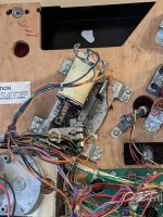
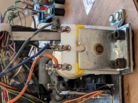
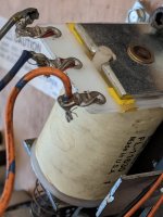
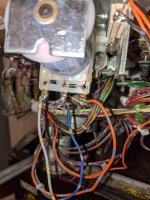
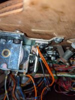
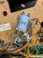
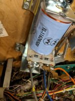
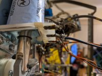
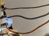
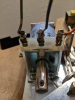
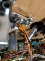
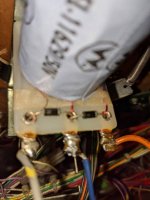
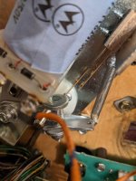
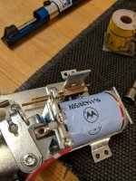
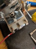
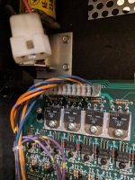
when you rebuilt the flipper you fitted the new coil with the solder tabs in the traditional way at the plunger end, the original coil was mounted with the solder lugs at the coil stop end, so you re soldered the wires in there original orientation but the coil has now turned 180 degrees so the orange and gray wires are now on the wrong lugs.
Do what Chris B said above and you should be all good again.
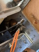
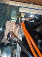
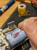
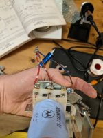
if when the meter is on diode mode it reads 0 or very close to it, the diode is dead and need to be replaced (taking care the diode band is the same end when you fit it). anything above 0.450 (red lead on the non-banded end) should be ok, check by putting the meter leads on the diode both ways round to confirm it
if you have another coil to fit on the other side, then compare the readings on your meter from both and in all meter probe orientations as a double check if your not sure or unfamiliar with what readings you should be seeing on it?


") but now I know to look at the banding, hopefully won't get cuaght out again
but now I know to look at the banding, hopefully won't get cuaght out again
