What's new
Pinball info

Register a free account today to become a member! Once signed in, you'll be able to participate on this site by adding your own topics and posts, as well as connect with other members through your own private inbox!

Its alive!!! Strikes n Spares. Playfield lights issue.

Ed209

Registered
Joined
Jul 19, 2019
Messages
25
Location
Ramsgate
Hey all

So this morning I had my first game on my bally strikes n spares! A little fuse here and some inaugural crimping efforts and it's on!

A few things to sort still which I know what to do e.g. levelers are rusted so need to get them off and replace as at present the game is stuck at a blistering 3 degree incline! The coin door is missing the bit where the money triggers the game but the good news is the replay is set really low so a score of 50000 seems to get me 30 credits.

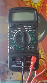
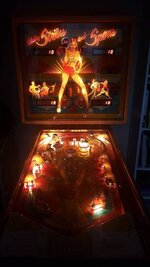
One thing that I'm not so sure on is all the playfield lights below the board appear to not be working - some of the lights on the playfield work around the bumpers and other table features. But all the lights for the bonuses on the playfield etc dont work. I did the first self test and nothing happened, no lights flashed (the 2nd one got the score boards checked, the 3rd fired off the various solenoids etc).Checked out the connectors on the light circuit board and they look ok... I could get crimping on those and replace them? I havent run a voltage test on the fuses on the rectifier board that actually worked yet - I don't think I had the right setting on the voltmeter. I know all but j4 are DC. So maybe they are not getting enough juice? Any ideas if it's anything else?

Really enjoying this process, cheers Ed
 

Attachments

  • IMG_20190908_200252_995.jpg
    IMG_20190908_200252_995.jpg
    57.6 KB · Views: 24
How is Fuse 1 on the transformer rectifier board?
Check between Test point 1 and ground on the board.
You should have around 5.5 vdc there.
 
If you look at the controlled lamps you’ll see that there is a common wire to them all. This wire should permanently be at 6v or so. Each lamp then had ground switched onto it.

So if there’s no 6v you have a power supply issue.

If you have 6v then you have a lamp driving issue.

Either the data signals are not getting from the cpu to the lamp driver board

Or

The logic on the lamp driver board is bad

Or

All the controlled lamps are blown or have bad sockets.
 
Bugger. Did a test of the fuses and read 0 off of F1 on the rectifier board. Then thought as it was on I'd have a cheeky game... during play there was a pop from the rectifier board and the scoring all went out. It looks like F5 on the rectifier is chips and now on start up I get only one green flash from the mpu :( ballsville.
 
Wow.

So it turns out that whatever blew on the rectifier board pushed some of the connector pins out of the J1 wafer on my rectifier board! I pushed them back in to the wafer and now have got the general illumination back on, a bunch of green lights on the MPU on start up and the start up jingle. The score boards flash on for a bit then go off again. Until I get new fuses and test the rectifier board fuse output I'm not going to fart around any more with anything else! lesson learned!

Anyone got a link on how to test rectifier fuses with a voltmeter? I set my voltmeter to 200VDC for fuses F1,F2,F3,F5 & F6. But wasn't quite sure what to set it to for F1 as thats to be an AC check?
 
Have you found this yet, it's the repair guide that covers your machines containing a plethora of invaluable information and describes the Test Points on the rectifier board (also in the manual on Power Transformer schematic digital page 43).
http://techniek.flipperwinkel.nl/ballyss/rep/index1.htm

TP4 is 7.3 VAC for GI - your meter likely has an AC range, post a pic of it if you're not sure and people will help 👍

Yeah, that's a great link and it's been super helpful.

This is the voltmeter I got on Ebay that took so long to arrive i got it for free! I've been using it on 200vdc for the rectifier fuses with the black on ground cable in back box and red on the various test point loops on the rectifier. Before the machine went whacko I got:
f1 as 0,
f2 as 159.3 (with J2 plugged in only),
f3 as 11.8 (with J2 plugged in only),
f4 as 06.6
f5 as 46.3.

Tested the F1 fuse for continuity and it works. So looking up why no current is coming through F1.
 

Attachments

  • 20190912_163921.jpg
    20190912_163921.jpg
    61 KB · Views: 12
Last edited:
The 2 positions clockwise are your AC ranges. I set the DC range just above what I expect to measure so 20V setting for TP3, TP1 for example. Other stuff you'd use is the Ohms for Resistance (green settings bottom left) and mostly the continuity, red setting at 5 o'clock position. A bit unusual yours has diode testing (useful) on that same setting which are separate on mine.

Excuse me if you know all this 👍
 
Cheers Astyyy. Yeah still no current out of f1 and the fuse has continuity. Read online it could be the BR1. Trying to Google how to test that now. Also going to look up why the current is so low on f2.
 
Hey, its me I'm back! The central scrutinizer!

So I got some time to test BR1 on the rectifier board, doing the thing I saw here (
) and it read zilch. So thinking I need to replace BR1. To match the spacing to BR2 and BR3 it looks like I need a part called KBPC3504W which is a newer better BR1 that is the width of the original one fitted. I am hoping that my general illumination error stems from zero power coming through F1 via BR1.

So how hard is it to swap over BR1? as it only costs a fiver.

Finally after my playing around I've successfully got the scoreboards from not working since the POP of F5 (the scores power up, a 0 flashes and then an _ is in the bottom right). I've also successfully stopped the start play button working (the add credit switch inside the coin door still adds credit though).

But..... it still looks great! ;)
 
Back
Top Bottom